How to Improve Cutting Quality on a Laser Cutting Machine in Metal Fabrication: The Ultimate Technical Guide


Technical Overview: Understanding Laser Cutting Dynamics
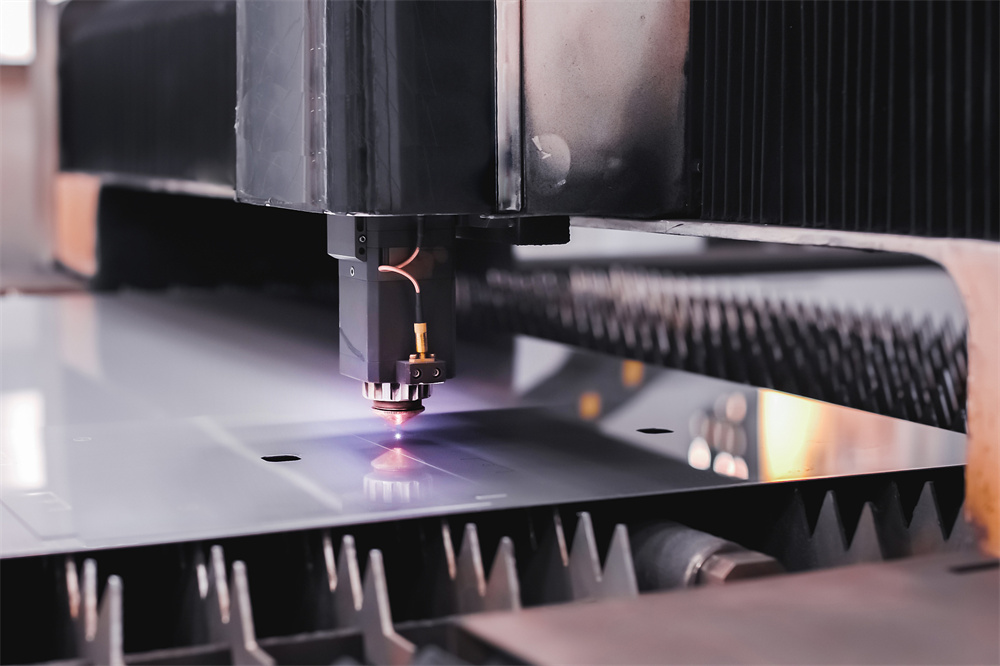
In the modern landscape of metal fabrication, achieving superior edge quality is the hallmark of a high-performing workshop. To improve cutting quality on a laser cutting machine in metal fabrication, operators must first understand the fundamental interaction between the laser beam, the assist gas, and the workpiece material. A laser cutting machine functions by focusing a high-intensity beam onto a precise point, melting or vaporizing the metal, while a high-pressure gas stream clears the molten material from the kerf.
The quality of the cut is defined by several critical factors: surface roughness, dross formation, perpendicularity, and the width of the heat-affected zone (HAZ). When these variables are not perfectly balanced, the resulting parts may require secondary processing, such as grinding or deburring, which significantly increases production costs and lead times. By optimizing the machine’s technical parameters, fabricators can achieve “finish-cut” quality that requires no further intervention.
Fiber laser technology has revolutionized the industry, offering higher speeds and better energy efficiency compared to traditional CO2 lasers. However, the increased power density of fiber lasers requires more precise control over focal position and gas dynamics. Understanding the synergy between the laser source, the CNC controller, and the optical delivery system is essential for any operator looking to refine their output.
Furthermore, the environmental conditions of the fabrication facility play a role. Humidity, ambient temperature, and the purity of the assist gas can all influence the consistency of the cut. A comprehensive approach to quality improvement involves not just adjusting machine settings, but also maintaining a clean, stable environment for the equipment to operate within its optimal design parameters.
Core Parameters for Optimal Performance
To improve cutting quality on a laser cutting machine in metal fabrication, one must master the “Big Four” parameters: laser power, cutting speed, focal position, and assist gas pressure. Each of these variables acts as a lever that, when adjusted, directly impacts the physical characteristics of the cut edge. Balancing these levers is an iterative process that depends on the material type, thickness, and the specific laser source wattage.
Laser power determines the amount of energy delivered to the material. If the power is too low, the laser will fail to penetrate the material fully, resulting in incomplete cuts or heavy dross. Conversely, excessive power can cause the material to overheat, leading to a wider kerf and increased HAZ. Finding the “sweet spot” involves matching the power output to the material’s thermal conductivity and thickness.
Cutting speed is intrinsically linked to power. If the speed is too high for the given power level, the laser beam will lag behind, creating a curved striation pattern and potential burrs on the bottom edge. If the speed is too slow, the laser dwells too long on a single point, causing excessive melting and widening the kerf. The goal is to maintain a constant feed rate that allows the beam to vaporize material efficiently without overheating the surrounding area.
Focal position—the distance between the focal point of the laser beam and the surface of the workpiece—is perhaps the most sensitive parameter. A positive focal position (above the surface) is often used for thicker materials to ensure a wider kerf and better gas flow, while a negative focal position (below the surface) is typically used for thinner materials to achieve a narrower, cleaner cut. Adjusting this position by even a fraction of a millimeter can be the difference between a perfect edge and a rejected part.
Assist gas pressure and nozzle selection are the final pieces of the puzzle. Oxygen is typically used for mild steel to create an exothermic reaction that aids the cutting process, while nitrogen is used for stainless steel and aluminum to prevent oxidation and ensure a clean, bright finish. The nozzle diameter must be matched to the material thickness to ensure the gas stream is laminar and effective at ejecting molten metal.
Calculation Method for Parameter Optimization
Calculating the ideal cutting parameters is not merely a matter of guesswork; it involves a systematic approach based on material properties and machine capabilities. To improve cutting quality on a laser cutting machine in metal fabrication, operators should utilize a “Design of Experiments” (DoE) approach. This involves creating a test matrix where one variable is changed at a time while keeping others constant to observe the specific effect on the cut edge.
The first step in the calculation process is determining the “Energy Density” required for the specific material. This is calculated by dividing the laser power (in Watts) by the product of the cutting speed (in mm/min) and the beam spot size (in mm). By maintaining a consistent energy density across different thicknesses, operators can create a baseline for their cutting charts.
Next, calculate the gas flow requirements. The gas pressure should be sufficient to clear the molten material but not so high that it creates turbulence in the kerf. A common method is to start with the manufacturer’s recommended settings and perform a “test cut” on a scrap piece of the same material. Inspect the striation lines; if they are vertical and smooth, the parameters are likely optimal. If they are slanted or jagged, adjustments to the speed-to-power ratio are required.
Finally, consider the duty cycle and pulse frequency. For thinner materials, high-frequency pulsing can prevent heat buildup and improve edge quality. For thicker materials, continuous wave (CW) mode is generally preferred to maintain deep penetration. By documenting these calculations in a digital logbook, fabricators can build a library of “Golden Settings” for every material and thickness they process regularly.

Parameter Table: Baseline Settings for Common Materials
The following table provides a starting point for common materials. Please note that these values are approximations and should be adjusted based on your specific laser source and machine configuration.
| Material | Thickness (mm) | Power (W) | Speed (m/min) | Gas Type | Pressure (bar) |
|---|---|---|---|---|---|
| Mild Steel | 3.0 | 2000 | 4.5 | Oxygen | 0.6 |
| Mild Steel | 6.0 | 3000 | 2.2 | Oxygen | 0.4 |
| Stainless Steel | 2.0 | 2000 | 6.0 | Nitrogen | 12.0 |
| Stainless Steel | 5.0 | 4000 | 2.5 | Nitrogen | 16.0 |
| Aluminum | 3.0 | 3000 | 3.5 | Nitrogen | 14.0 |
Common Engineering Mistakes in Laser Cutting
Even with advanced machinery, common mistakes can undermine the goal to improve cutting quality on a laser cutting machine in metal fabrication. One of the most frequent errors is neglecting the condition of the protective lens. A dirty or pitted lens will scatter the laser beam, resulting in a loss of power density and poor cut quality. Operators should implement a strict cleaning schedule and inspect the lens before every shift.
Another common mistake is the improper alignment of the beam. If the laser beam is not perfectly centered in the nozzle, the gas flow will be uneven, leading to inconsistent edges and potential damage to the nozzle itself. Regular beam alignment checks are mandatory for maintaining precision. Furthermore, using worn-out nozzles can cause gas turbulence, which disrupts the cutting process and leaves burrs on the bottom of the sheet.
Ignoring the material quality is also a significant oversight. Using rusted, oily, or unevenly coated metal can cause the laser to reflect or absorb energy inconsistently. Always ensure that the material surface is clean and that the sheet is properly leveled on the machine bed. A warped sheet can cause the focal distance to change during the cut, leading to inconsistent edge quality across the part.
Finally, failing to update the software or firmware of the CNC controller can prevent the machine from utilizing the latest optimization algorithms. Modern laser controllers are capable of dynamic power adjustment during corners and complex geometries. If these features are not enabled or correctly configured, the machine will likely overheat the corners of the part, leading to “burn-through” or rounded edges.
Selection Checklist for High-Quality Fabrication
When selecting equipment or accessories to improve cutting quality on a laser cutting machine in metal fabrication, use this checklist to ensure you are making the right investments:
- Laser Source Stability: Does the laser source provide a stable beam profile across the entire power range?
- Auto-Focus Head: Does the machine feature an automated focal position adjustment system for rapid material changes?
- Gas Purity Monitoring: Are you using high-purity assist gases? Impurities can cause oxidation and poor edge finish.
- Chiller Performance: Is the cooling system capable of maintaining a constant temperature for the laser source and optics?
- Software Integration: Does your CAM software support advanced lead-in/lead-out strategies to minimize edge defects?
- Maintenance Schedule: Do you have a documented preventative maintenance plan for optics, nozzles, and filters?
- Operator Training: Is your team trained on the specific nuances of your machine’s control interface?
FAQ: Frequently Asked Questions
Why is there dross on the bottom of my cut?
Dross is usually caused by either too much heat (slow speed) or insufficient gas pressure to blow the molten metal away. Try increasing the cutting speed or adjusting the gas pressure slightly.
How often should I clean the protective lens?
The protective lens should be inspected daily. If you notice any dust, fingerprints, or pitting, clean it immediately with lens-grade cleaning solution and lint-free wipes.
Does the nozzle size affect cutting quality?
Yes, the nozzle diameter must be matched to the material thickness. A nozzle that is too large will reduce gas pressure, while one that is too small may restrict the gas flow and cause overheating.
Why are my corners burning?
Corner burning occurs when the machine slows down at a sharp turn, causing the laser to dwell too long. Ensure your CNC controller has “corner power reduction” settings enabled to lower the laser power during deceleration.
Can I use shop air for laser cutting?
While shop air can be used for some applications, it must be extremely clean, dry, and oil-free. Any contaminants in the air will damage the optics and ruin the cut quality. A dedicated air compressor and filtration system are highly recommended.