Press Brake Crowning Explained: How to Prevent Bending Deflection and Improve Consistency


Technical Overview: The Physics of Bending Deflection
In the world of precision metal fabrication, achieving a perfectly straight bend across the entire length of a workpiece is a significant engineering challenge. When a press brake applies force to a metal sheet, the laws of physics dictate that the machine’s components—specifically the upper ram and the lower bed—will experience a degree of deflection. This phenomenon occurs because the hydraulic cylinders are typically located at the ends of the machine, while the resistance from the metal sheet is distributed across the center. As a result, the center of the ram bows upward and the center of the bed bows downward, leading to what is commonly known as the ‘canoe effect.’
Without a compensation mechanism, the resulting bend angle will be inconsistent: the ends of the workpiece will meet the desired angle, but the center will be under-bent (wider angle). This inconsistency is particularly problematic for long parts or high-precision components used in aerospace, automotive, and structural engineering. Press brake crowning is the technical solution designed to counteract this deflection by introducing a slight curve into the bed or ram that mirrors the expected deflection under load.
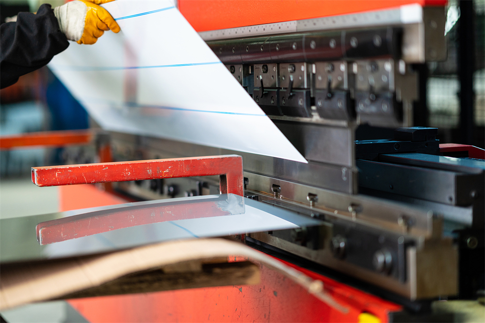
There are two primary types of crowning systems: hydraulic and mechanical. Hydraulic crowning utilizes a series of cylinders embedded within the lower table that apply upward pressure to compensate for the load. Mechanical crowning, on the other hand, uses a system of wedges or ‘waves’ that are adjusted via a motor or hand crank to create a physical crown in the table. Both systems aim to ensure that the punch and die remain parallel throughout the entire bending process, regardless of the tonnage applied.
Modern CNC press brakes, such as those manufactured by HARSLE, integrate crowning control directly into the machine’s software. By inputting material type, thickness, and length, the CNC controller calculates the required compensation in real-time. This automation has revolutionized the industry, allowing operators to achieve high-precision results without the need for manual shimming or extensive trial-and-error adjustments.
Core Parameters Influencing Crowning Requirements
To effectively manage press brake crowning, engineers must understand the core parameters that dictate how much deflection will occur. The first and most critical parameter is Material Tensile Strength. Higher-strength materials, such as stainless steel or high-tensile carbon steel, require significantly more force to bend. This increased tonnage leads to greater deflection in the machine frame, necessitating a more aggressive crowning adjustment compared to softer materials like aluminum.
The Length of the Bend is the second major factor. Deflection is not a linear problem; it increases exponentially with the length of the workpiece. A 4-meter press brake will experience much more significant ‘bowing’ than a 1.5-meter machine when performing a full-length bend. This is why crowning systems are almost mandatory for any machine with a bed length exceeding 2.5 meters, or for machines used in heavy-duty applications.
Material Thickness and V-Die Opening also play a pivotal role. Thicker materials require larger V-die openings and higher tonnages. The relationship between the V-die width and the material thickness determines the ‘bending force per meter.’ If an operator uses a V-die that is too narrow for the material thickness, the tonnage spikes, causing excessive deflection that may exceed the machine’s crowning capacity. Conversely, a V-die that is too wide reduces the force but may compromise the bend radius accuracy.
Finally, the Machine’s Structural Rigidity must be considered. Not all press brakes are built the same. A machine with a heavy-duty, stress-relieved frame will naturally deflect less than a lighter, budget-oriented model. HARSLE machines are engineered with high-rigidity frames to minimize passive deflection, ensuring that the active crowning system can work more efficiently to provide a perfect finish. Understanding these parameters allows operators to pre-emptively adjust settings for optimal consistency.
Calculation Method for Crowning Compensation
While modern CNC controllers handle the heavy lifting of calculations, understanding the underlying math is essential for troubleshooting and high-level engineering. The deflection of a press brake ram can be modeled using the beam deflection formula. In a simplified engineering context, the deflection (δ) is proportional to the force (P) and the cube of the length (L), and inversely proportional to the Modulus of Elasticity (E) and the Moment of Inertia (I).
The general formula used by many CNC algorithms is: C = (K * T * L^3) / (E * I), where C is the crowning compensation value, K is a constant specific to the machine’s frame design, T is the tonnage applied, and L is the length of the workpiece. Because the Moment of Inertia (I) varies depending on the cross-section of the ram and bed, each machine model has a unique ‘compensation curve’ programmed into its controller.
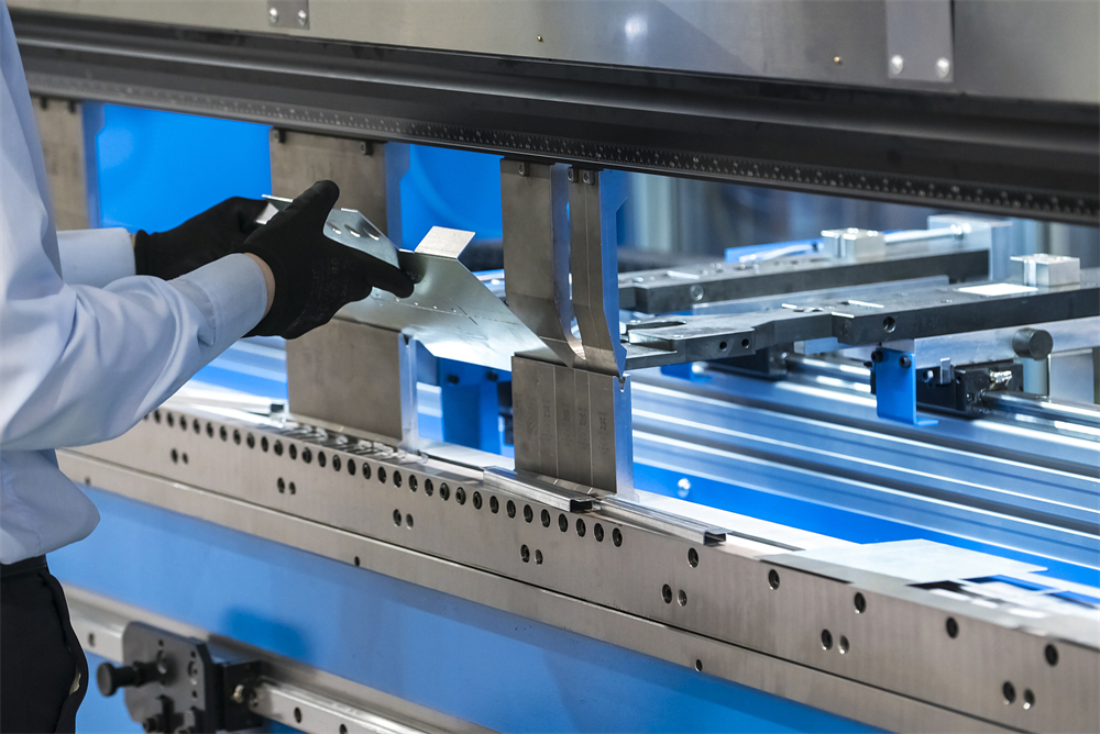
In practical application, operators often use a ‘Trial Bend’ method to fine-tune the calculation. For example, if a 3-meter sheet of 4mm mild steel is bent and the center angle is 92 degrees while the ends are 90 degrees, the operator knows that the current crowning setting is insufficient. The CNC allows for a ‘Crowning Offset’ to be entered, which shifts the entire compensation curve upward to close that 2-degree gap. This empirical data is then saved in the machine’s library for future use with similar materials.
It is also important to account for Springback. Springback is the tendency of the metal to return to its original shape after the pressure is released. While crowning addresses the physical deflection of the machine, it must work in tandem with the CNC’s springback compensation. If the crowning is correct but the springback is miscalculated, the part will still be out of tolerance. Therefore, the calculation method must be a holistic approach that considers both machine deformation and material behavior.
Parameter Table: Estimated Crowning Values
The following table provides estimated crowning compensation values for a standard 3100mm press brake. Note: These are reference values; actual settings depend on specific machine rigidity and tool condition.
| Material Type | Thickness (mm) | V-Die Opening (mm) | Tonnage (T/m) | Estimated Crowning (mm) |
|---|---|---|---|---|
| Mild Steel | 2.0 | 16 | 15 | 0.15 – 0.25 |
| Mild Steel | 4.0 | 32 | 35 | 0.40 – 0.60 |
| Mild Steel | 6.0 | 50 | 50 | 0.75 – 1.00 |
| Stainless Steel | 2.0 | 16 | 22 | 0.30 – 0.45 |
| Stainless Steel | 4.0 | 32 | 50 | 0.80 – 1.10 |
| Aluminum (5052) | 3.0 | 25 | 12 | 0.10 – 0.20 |
This table illustrates how crowning requirements scale with material strength and thickness. Stainless steel, having a higher yield strength than mild steel, requires nearly double the compensation for the same thickness. Operators should use these values as a starting point before performing fine-tuning on the CNC interface.
Common Engineering Mistakes in Crowning Management
One of the most frequent mistakes in metal fabrication is Over-Crowning. This occurs when the operator or the CNC system applies too much compensation, causing the center of the bend to be over-bent (a tighter angle than the ends). Over-crowning not only ruins the workpiece but can also put unnecessary stress on the machine’s crowning wedges or hydraulic seals. It is often caused by incorrect material data entry—for instance, entering the properties of stainless steel when bending mild steel.
Another common error is Ignoring Tooling Wear. Crowning systems assume that the punch and die are in perfect condition. However, if the center of a long V-die is worn down from repeated use, the crowning system will struggle to compensate for both the machine deflection and the tool wear. This often leads to inconsistent results that are difficult to diagnose. Regularly rotating or resurfacing tools is essential for maintaining the integrity of the crowning system’s output.
Incorrect V-Die Selection is also a major culprit. As mentioned earlier, using a V-die that is too small increases the required tonnage exponentially. If the tonnage exceeds the machine’s design limits, the frame may deflect beyond the crowning system’s physical ability to compensate. This ‘bottoming out’ of the compensation mechanism results in a permanent ‘canoe’ shape in the parts. Engineers must ensure that the chosen V-die is appropriate for the material thickness to keep the tonnage within the machine’s ‘sweet spot.’
Finally, many shops fail to perform Regular Calibration. Over time, the mechanical wedges in a crowning table can accumulate dust and debris, or hydraulic sensors can drift. If the machine thinks it is applying 0.5mm of crown but is actually only applying 0.3mm, the operator will constantly fight with angle consistency. A quarterly calibration of the crowning system against a precision straightedge is a best practice for high-volume fabrication shops.
Selection Checklist: Choosing the Right Crowning System
When purchasing a new press brake, selecting the right crowning system is as important as choosing the tonnage or the backgauge configuration. Use this checklist to evaluate your options:
- System Type: Decide between Hydraulic and Mechanical crowning. Mechanical systems (like the Wila-style) are often preferred for their precision and lack of ‘drift’ over long bending cycles, while hydraulic systems are excellent for high-speed, automated environments.
- CNC Integration: Ensure the crowning system is fully integrated with the CNC controller (e.g., Delem DA-66T or Cybelec). It should automatically calculate compensation based on the part program.
- Compensation Points: Look for a system with multiple compensation points across the bed. A ‘single-point’ crown is less effective than a ‘multi-wedge’ system that can create a more natural curve.
- Load Capacity: Verify that the crowning system’s maximum compensation exceeds the expected deflection for your heaviest materials.
- Maintenance Accessibility: Is the crowning mechanism easy to clean and lubricate? Systems that are completely sealed or easy to access will have a longer service life.
- Accuracy Specs: Ask the manufacturer for the crowning resolution. High-end systems can adjust in increments as small as 0.01mm.
HARSLE offers both hydraulic and mechanical crowning options across our range of CNC press brakes, ensuring that whether you are bending thin decorative panels or heavy structural plates, you have the tools necessary for perfect consistency.
Frequently Asked Questions (FAQ)
What is the ‘Canoe Effect’ in press brake bending?
The ‘Canoe Effect’ refers to a bend where the ends of the metal sheet are bent to the correct angle, but the center is under-bent, creating a bowed shape similar to a canoe. This is caused by the deflection of the machine’s ram and bed under high pressure.
Can I add a crowning system to an old press brake?
Yes, there are aftermarket mechanical crowning tables (often called ‘crowning beds’) that can be bolted onto existing machines. However, these usually require manual adjustment unless they can be interfaced with an upgraded CNC controller.
Is crowning necessary for short workpieces?
Generally, no. If the workpiece is short (e.g., less than 500mm) and placed in the center of the machine, the deflection is minimal. However, if you are bending short parts at one end of a long machine, you may encounter ‘off-center loading’ issues, which is a different structural challenge.
How do I know if my crowning is set correctly?
The best way is to perform a full-length test bend. Measure the angle at both ends and in the dead center. If all three measurements are identical, your crowning is perfectly calibrated. If the center is wider, increase crowning; if the center is tighter, decrease it.
Does crowning affect the backgauge accuracy?
Indirectly, yes. If the bed is significantly deflected or the crowning is poorly adjusted, the material may not sit perfectly flat against the backgauge fingers, leading to slight variations in the flange length. Proper crowning ensures the material remains level.