How to Reduce Burrs and Improve Edge Quality with a Punching Machine: A Comprehensive Technical Guide


Technical Overview of the Punching Process
In the world of metal fabrication, achieving a clean, precise cut is the hallmark of quality. When using a punching machine, the goal is to create a hole or a shape with minimal deformation and a smooth edge. However, the physical reality of shearing metal often leads to the formation of burrs—unwanted ridges or protrusions of material. To reduce burrs and improve edge quality with a punching machine, one must first understand the mechanics of the punching cycle. The process is generally divided into three distinct stages: elastic deformation, plastic deformation, and fracture.
During the initial contact, the punch applies pressure to the sheet metal, causing it to deform elastically. As the pressure increases, the material enters the plastic deformation stage, where it begins to flow into the die opening. This creates the ‘rollover’ or ‘radius’ at the top edge of the hole. Eventually, the internal stresses exceed the material’s ultimate tensile strength, leading to a fracture. If the machine parameters are optimized, the fractures from the punch side and the die side meet perfectly, resulting in a clean break. If they do not meet, the material is torn or dragged, creating a burr.
Burr height is a critical metric in quality control. A burr that is too large can interfere with subsequent assembly processes, cause safety hazards for handlers, and lead to premature failure of the finished part due to stress concentrations. Improving edge quality involves balancing the shear zone (the shiny, burnished part of the edge) and the fracture zone (the rougher, matte part of the edge). High-quality punching aims for a shear zone that occupies approximately one-third of the material thickness, with a clean fracture for the remainder.
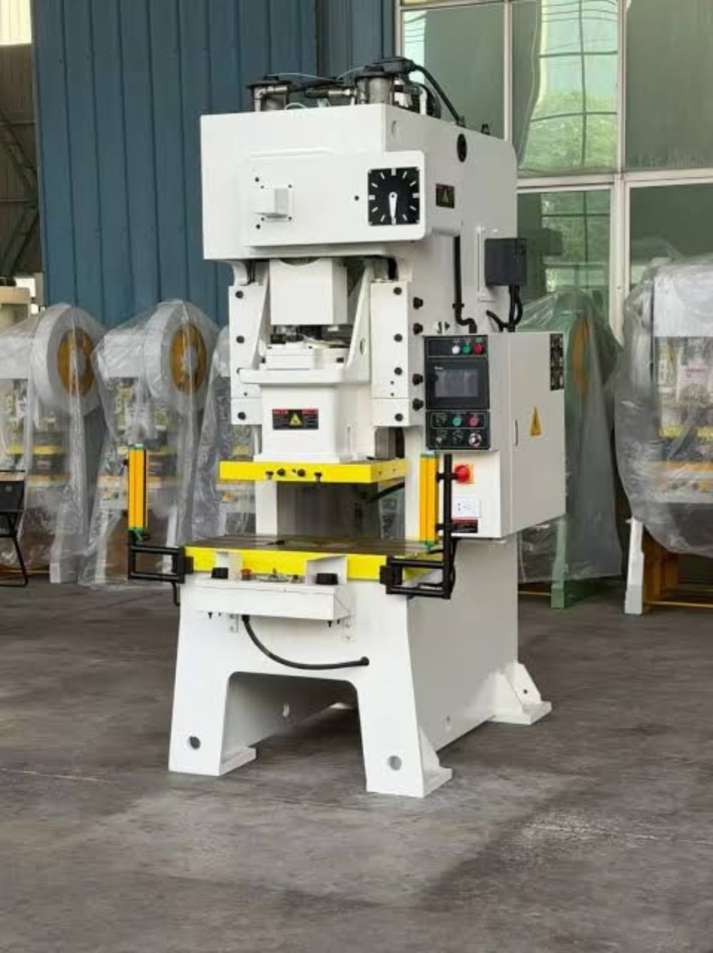
Furthermore, the rigidity of the punching machine itself plays a vital role. A machine with a high-strength frame, such as those manufactured by HARSLE, minimizes deflection during the high-tonnage impact of the punch. Frame deflection can cause the punch to enter the die at a slight angle, leading to uneven clearance and, consequently, inconsistent edge quality across the workpiece. Therefore, maintaining machine alignment and structural integrity is the foundation of burr reduction.
Core Parameters Influencing Edge Quality
To effectively reduce burrs and improve edge quality with a punching machine, operators and engineers must focus on several core parameters. The most significant of these is die clearance. Die clearance is the total space between the punch and the die. It is usually expressed as a percentage of the material thickness. If the clearance is too tight, the fracture lines do not meet, causing a secondary shear or ‘double burnish,’ which increases tool wear and creates a jagged edge. Conversely, if the clearance is too large, the material is pulled into the die, resulting in a large rollover and a heavy burr.
Tool sharpness is the second most critical factor. A dull punch or die does not cut the metal; it pushes it. This increased friction and pressure lead to excessive heat and material dragging, which are the primary drivers of burr formation. Regular sharpening schedules are essential. It is often more cost-effective to sharpen tools frequently by removing a small amount of material (0.1mm to 0.2mm) than to wait until the tool is severely rounded, requiring a significant grind-down that shortens the tool’s overall lifespan.
Lubrication also plays a silent but vital role in edge quality. Proper lubrication reduces the friction between the punch and the workpiece, as well as between the slug and the die. This reduction in friction prevents ‘galling’—a condition where bits of the workpiece material weld themselves to the punch tip. Galling changes the effective geometry of the tool, leading to poor edge quality and increased stripping force. Using a high-quality vanishing oil or a specialized punching lubricant can significantly extend tool life and improve the aesthetic of the cut edge.
Finally, the stroke speed and the dwell time of the punching machine can influence the result. In high-speed CNC punching, the rapid impact can sometimes lead to cleaner fractures in brittle materials but may cause excessive heat in softer alloys like aluminum. Modern HARSLE machines allow for fine-tuning of the hydraulic or servo-electric stroke, enabling operators to match the punching speed to the specific characteristics of the material being processed.
Calculation Method for Optimal Die Clearance
Determining the correct die clearance is not a matter of guesswork; it is a technical calculation based on the material’s thickness and its mechanical properties. The general formula for total die clearance (C) is:
C = t × k
Where:
t = Material Thickness
k = Clearance Factor (expressed as a decimal)
The clearance factor ‘k’ varies depending on the material type. For standard mild steel, the ‘k’ factor typically ranges from 15% to 20% of the material thickness for general-purpose punching. However, for high-precision applications where edge quality is paramount, this might be adjusted. For example, stainless steel, which is tougher and tends to work-harden, requires a larger clearance (often 20% to 25%) to allow the fracture to propagate correctly without excessive tool stress. Aluminum, being softer and more ductile, might require a tighter clearance (10% to 15%) to prevent excessive rollover.
It is important to note that ‘total clearance’ refers to the difference between the die diameter and the punch diameter. If you are calculating ‘clearance per side,’ you would divide the total clearance by two. For instance, if you are punching 2mm thick mild steel with a recommended total clearance of 20%, the total clearance would be 0.4mm. This means if your punch is 10mm, your die should be 10.4mm.
Advanced fabricators often use ‘engineered clearances’ to achieve specific edge characteristics. If a part requires a larger burnished area for a bearing surface, a tighter clearance is used. If the part is to be painted or powder-coated and the edge quality is less critical than tool life, a slightly larger clearance might be chosen to reduce the tonnage required and minimize tool wear. Always consult the material’s shear strength data to refine these calculations.
Recommended Die Clearance Parameter Table
The following table provides a starting point for selecting the total die clearance based on material type and thickness. These values are optimized to reduce burrs and improve edge quality with a punching machine under standard industrial conditions.
| Material Type | Thickness (mm) | Recommended Total Clearance (%) | Total Clearance Value (mm) | Expected Edge Quality |
|---|---|---|---|---|
| Mild Steel (CR4/DD11) | 1.0 | 15% | 0.15 | Excellent, minimal burr |
| Mild Steel (CR4/DD11) | 2.0 | 18% | 0.36 | Clean fracture, low rollover |
| Mild Steel (CR4/DD11) | 3.0 | 20% | 0.60 | Standard industrial finish |
| Stainless Steel (304/316) | 1.0 | 20% | 0.20 | High burnish, requires sharp tools |
| Stainless Steel (304/316) | 2.0 | 22% | 0.44 | Reduced work-hardening at edge |
| Aluminum (5052/6061) | 1.5 | 12% | 0.18 | Smooth edge, minimal dragging |
| Aluminum (5052/6061) | 3.0 | 15% | 0.45 | Low rollover, clean break |
| Galvanized Steel | 1.2 | 16% | 0.19 | Prevents coating flaking |
Note: These percentages are based on the material thickness. For materials thicker than 6mm, it is often recommended to increase the clearance slightly to account for the increased tonnage and potential tool deflection. Always perform a test punch on a scrap piece of the same material before starting a production run.
Common Engineering Mistakes in Punching
Even with high-end equipment, certain common mistakes can undermine the effort to reduce burrs and improve edge quality with a punching machine. One of the most frequent errors is neglecting tool alignment. Even if the clearance is calculated correctly, if the punch is not perfectly centered within the die, the clearance becomes uneven. One side of the hole will have too little clearance (causing double shear), while the other side will have too much (causing a large burr). This is often caused by worn turret bushings or improper tool installation.
Another mistake is the ‘one-size-fits-all’ approach to die selection. Using the same die for 1mm and 2mm steel might seem like a time-saver, but it is a recipe for poor quality. The 2mm steel will suffer from excessive burrs because the clearance (optimized for 1mm) is far too tight. This not only ruins the edge quality but also puts immense strain on the machine’s hydraulic system and the tool itself, leading to premature failure.
Ignoring the material’s grain direction is a subtle but impactful mistake. Like wood, rolled metal has a grain direction. Punching across the grain or along the grain can result in slightly different fracture patterns. For high-precision parts, orienting the nests to account for grain direction can help in achieving consistent edge quality across all parts in a batch. Furthermore, failing to account for the ‘slug pull’—where the waste material sticks to the punch and is pulled back up—can lead to surface scratches and edge damage on the next hit.
Finally, many shops fail to implement a rigorous maintenance schedule for their punching machines. Hydraulic leaks, worn-out dampers, and loose gibs can all lead to vibration and inconsistent punching force. A machine that vibrates excessively will never produce a clean edge. HARSLE recommends a weekly inspection of the tool holders and a monthly check of the machine’s leveling and alignment to ensure peak performance.
Selection Checklist for a High-Quality Punching Machine
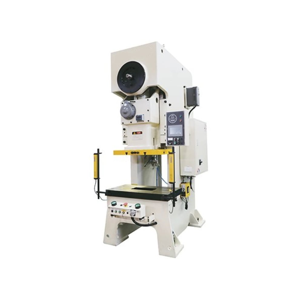
When looking to invest in a machine that will consistently reduce burrs and improve edge quality with a punching machine, consider the following checklist. Not all machines are created equal, and specific features can make a significant difference in your output quality.
- Frame Rigidity: Look for an O-frame or a heavily reinforced C-frame design. HARSLE’s O-frame models provide superior resistance to deflection, ensuring the punch and die stay aligned under load.
- CNC Control Precision: Ensure the controller can handle micro-adjustments for stroke depth. Being able to control exactly how far the punch enters the die can help in managing the fracture zone.
- Auto-Index Stations: Machines with auto-index capabilities allow the tool to rotate, enabling complex shapes to be cut with standard tools while maintaining the optimal angle relative to the material grain.
- Hydraulic Overload Protection: This feature protects the machine and the tools from damage if an incorrect material thickness or a dull tool is used, indirectly ensuring that quality isn’t compromised by machine fatigue.
- Tool Lubrication System: An integrated automatic tool lubrication system ensures that every hit is lubricated, reducing heat and preventing material galling.
- Brush Tables vs. Ball Tables: For sensitive materials like stainless steel or pre-painted aluminum, brush tables prevent scratching the underside of the sheet, which is essential for overall part quality.
- Fast Hit Rates: While speed isn’t everything, a machine that can maintain precision at high hit rates (e.g., 600-1000 hits per minute) demonstrates high-quality servo and hydraulic integration.
Frequently Asked Questions (FAQ)
1. Why do I get burrs on only one side of the punched hole?
This is almost always a sign of misalignment. The punch is not entering the center of the die, causing the clearance to be tighter on one side and wider on the other. Check your tool holders, turret alignment, and ensure the die is seated correctly in its holder.
2. How often should I sharpen my punching tools?
A general rule of thumb is to sharpen the tool when the radius of the cutting edge reaches 0.1mm to 0.15mm. In practical terms, for mild steel, this might be every 50,000 to 100,000 hits. However, for stainless steel, you may need to sharpen every 20,000 hits to maintain edge quality.
3. Can I reduce burrs by changing the punching speed?
Yes, to an extent. For softer materials, a slower, more controlled stroke can reduce the ‘dragging’ effect. For harder materials, a faster impact can sometimes encourage a cleaner fracture. Modern CNC punching machines allow you to experiment with these settings.
4. What is the ‘burnish’ or ‘shear’ zone?
The burnish zone is the shiny, smooth part of the edge created when the punch first enters the material. Ideally, this should be about 1/3 of the material thickness. If it’s more than that, your clearance is likely too tight.
5. Does the type of lubricant matter?
Absolutely. Using a lubricant specifically designed for metal punching reduces friction and heat much more effectively than general-purpose oils. This prevents the material from sticking to the punch, which is a major cause of burrs and poor edge quality.
6. How does material hardness affect burr formation?
Harder materials tend to fracture more cleanly but put more stress on the tools. Softer, more ductile materials (like soft aluminum or copper) tend to flow and stretch before they break, which naturally leads to larger rollovers and potential burrs if the clearance isn’t perfectly tuned.
7. Is it possible to eliminate burrs entirely?
While you can significantly reduce them to the point where they are negligible for most industrial applications, a mechanical punching process will almost always have a microscopic burr. For 100% burr-free edges, secondary processes like deburring or using a fiber laser might be necessary, though punching remains much faster and more cost-effective for many shapes.