Punching Machine Automation Guide: Feeding Systems, Controls, and Workflow Integration


Technical Overview of Punching Machine Automation
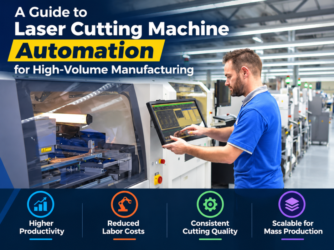
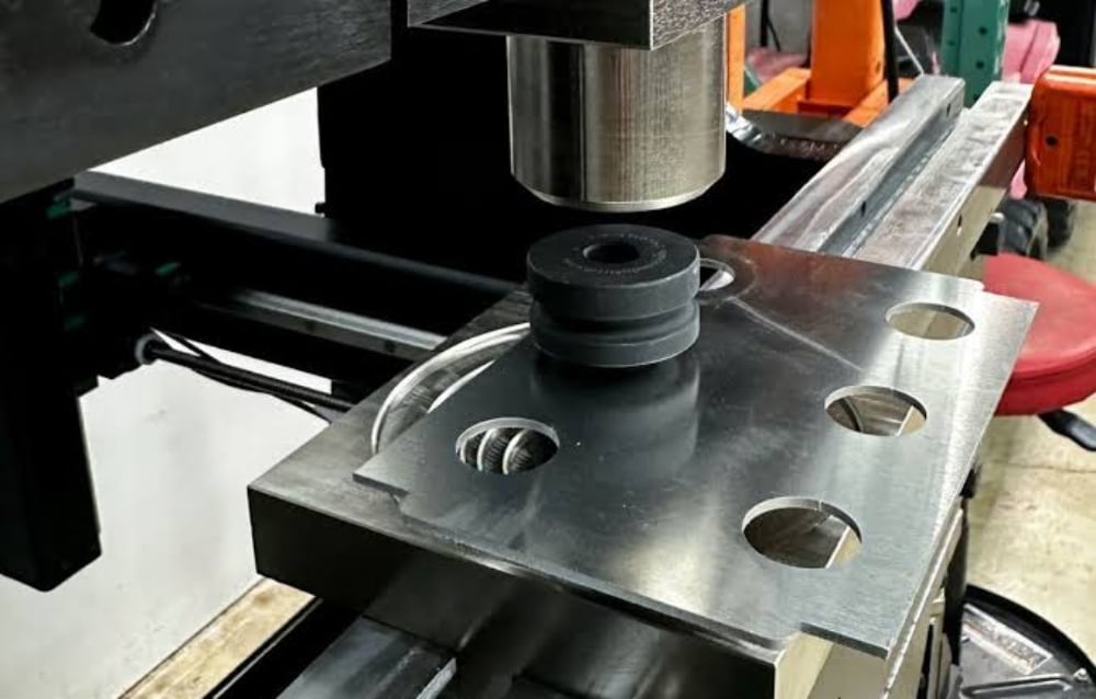
In the modern era of metal fabrication, the transition from manual operation to fully integrated Punching Machine Automation : Feeding Systems, Controls, Workflow Integration has become a necessity rather than a luxury. Automation in punching processes involves the synchronization of mechanical force with sophisticated electronic controls to achieve high-speed, high-precision production. At its core, an automated punching cell consists of the press itself, a material handling system (feeding), and a centralized control unit that manages the entire sequence of operations.
The evolution of this technology has been driven by the demand for tighter tolerances and higher throughput. Traditional mechanical presses required manual positioning, which was prone to human error and safety risks. Today, HARSLE and other industry leaders utilize NC (Numerical Control) servo feeders that communicate directly with the press’s PLC (Programmable Logic Controller). This ensures that the material moves exactly the required distance within milliseconds of the punch cycle completing. The integration of sensors and feedback loops allows the system to detect misfeeds or material defects instantly, preventing costly tool damage.
Furthermore, automation extends beyond just moving the metal. It encompasses the entire lifecycle of the workpiece, from the decoiling of raw steel to the stacking of finished parts. By implementing a seamless workflow, manufacturers can reduce idle time—the period when the machine is not actively punching—by up to 80%. This technical synergy is what defines a world-class fabrication facility, allowing for 24/7 operation with minimal human intervention.
The Role of Feeding Systems in Automation
The feeding system is the heartbeat of punching machine automation. It is responsible for the precise advancement of the material (usually coil or sheet) into the die area. There are several types of feeding systems, but the NC Servo Feeder is the industry standard for high-performance applications. These systems use high-torque brushless motors to drive rollers that grip the material. The precision of these motors allows for feed accuracies within ±0.02mm, which is essential for complex multi-stage progressive dies.
Beyond the feeder itself, a complete automated line often includes a decoiler and a straightener. The decoiler holds the heavy metal coils, while the straightener removes the “coil set” or curvature inherent in rolled metal. If the material is not perfectly flat before it enters the punching machine, the final parts will be warped, and the automation sensors may trigger false alarms. 3-in-1 systems, which combine the decoiler, straightener, and feeder into a single compact unit, are increasingly popular in facilities where floor space is at a premium.
Core Parameters of Automated Punching Systems
When evaluating Punching Machine Automation : Feeding Systems, Controls, Workflow Integration, several core parameters dictate the system’s capability and compatibility with specific production goals. The first is the Feed Pitch, which is the distance the material moves between each stroke. In high-speed lines, the feed pitch must be calculated in conjunction with the press’s SPM (Strokes Per Minute) to ensure the material has come to a complete stop before the punch makes contact.
Another critical parameter is Material Width and Thickness. Automated systems are rated for specific ranges; exceeding these can lead to slippage in the feeder rollers or motor stalls. The Feed Speed, usually measured in meters per minute, must be synchronized with the acceleration and deceleration curves of the servo motor to prevent marking the material surface. High-speed feeding requires specialized coatings on the rollers, such as polyurethane or chrome plating, to maintain grip without damaging aesthetic finishes.
Finally, the Control Response Time is a parameter often overlooked by buyers. This refers to the speed at which the feeder receives the “signal to move” from the press. In modern CNC systems, this communication happens via high-speed industrial Ethernet or fiber optics, minimizing the delay to microseconds. This rapid communication is what allows machines to operate at speeds exceeding 600 strokes per minute in specialized lamination or connector applications.
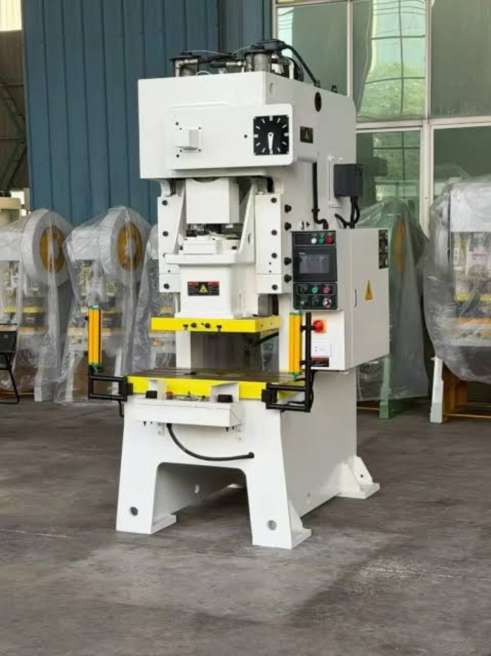
Workflow Integration and Software Logic
Workflow integration is the “brain” that connects the physical machinery to the factory’s digital ecosystem. This involves the use of CAD/CAM software to design parts and nesting software to optimize material usage. In an automated setup, the nesting software generates a program that tells the punching machine exactly where to hit and tells the feeder exactly how far to move. This data is often transferred via a local network or USB directly to the machine’s HMI.
Modern integration also includes IoT (Internet of Things) capabilities. HARSLE machines, for instance, can be equipped with modules that track production counts, downtime causes, and maintenance schedules in real-time. This data can be fed into an ERP (Enterprise Resource Planning) system, allowing management to see the exact cost per part and the efficiency of the production line. This level of integration ensures that the punching machine is not an isolated island of automation but a connected component of a smart factory.
Calculation Method for Automation Efficiency
To optimize an automated punching line, engineers must perform several key calculations. The most fundamental is the Total Cycle Time (TCT). This is calculated as the sum of the punch time, the feed time, and the dwell time. The formula is generally expressed as: TCT = (60 / SPM) + (Feed Length / Feed Speed) + Safety Buffer. Minimizing the safety buffer through precise control integration is the primary goal of automation engineering.
Another vital calculation is the Shear Force Requirement. While the automation handles the movement, the press must have enough tonnage to execute the cut. The formula is: Force (kN) = Perimeter of Cut (mm) × Material Thickness (mm) × Shear Strength (N/mm²). When integrating automation, one must ensure that the feeder can handle the weight of the material required for high-tonnage jobs, as heavier materials increase the inertia that the servo motor must overcome during start-stop cycles.
Lastly, the Material Utilization Rate is calculated to justify the cost of nesting software integration. By comparing the area of the finished parts to the total area of the raw coil used, manufacturers can determine the “scrap percentage.” Automated systems with advanced nesting can often improve utilization by 10-15%, which, over the course of a year, can save tens of thousands of dollars in raw material costs.
Parameter Table for Automation Selection
| Feature/Parameter | Entry-Level Automation | Mid-Range Industrial | High-Speed Precision |
|---|---|---|---|
| Feeder Type | Pneumatic / Mechanical | NC Servo Feeder | High-Speed Servo (Dual Drive) |
| Max Feed Speed | 15 – 20 m/min | 30 – 60 m/min | Up to 120 m/min |
| Positioning Accuracy | ±0.1 mm | ±0.05 mm | ±0.01 mm |
| Control System | Basic PLC / Relay | Touchscreen HMI + PLC | Integrated CNC + IoT Cloud |
| Material Handling | Manual Loading | Decoiler + Straightener | Full 3-in-1 Automated Line |
| Workflow Integration | Manual Data Entry | USB / LAN Program Load | Full ERP/MES Integration |
Common Engineering Mistakes in Punching Automation
One of the most frequent mistakes in Punching Machine Automation : Feeding Systems, Controls, Workflow Integration is the mismatch between the feeder’s capacity and the material’s inertia. Engineers often select a feeder based solely on the material width, forgetting that a heavy coil requires significant torque to accelerate. If the servo motor is undersized, it will result in “feed lag,” where the material doesn’t reach the target position before the punch descends, leading to broken tools and wasted material.
Another common error is poor sensor placement and calibration. In an automated workflow, sensors are the only “eyes” the machine has. If the end-of-material sensor or the misfeed detection sensor is improperly positioned, the machine may continue to cycle even when a jam has occurred. This can lead to catastrophic failure of the die set. Regular calibration and the use of high-quality inductive or optical sensors are non-negotiable for reliable automation.
Finally, many facilities fail to account for the “loop” requirement. Between the straightener and the feeder, there must be a slack loop of material. This loop acts as a buffer, allowing the feeder to pull material rapidly without having to pull the entire weight of the coil from the decoiler. If the loop is too short, the feeder will struggle against the tension; if it is too long, the material may drag on the floor and become scratched or contaminated. Automated loop control using ultrasonic sensors is the best way to mitigate this issue.
Selection Checklist for Automation Systems
- Material Compatibility: Does the feeder handle your maximum and minimum thickness and width?
- Speed Matching: Can the feeding system keep up with the maximum SPM of your punching press?
- Accuracy Requirements: Does the positioning tolerance meet your most stringent part specifications?
- Software Compatibility: Can the control system import files from your existing CAD/CAM software?
- Space Constraints: Do you have room for a full line, or do you need a compact 3-in-1 system?
- Safety Features: Does the system include light curtains, emergency stops, and interlocked guarding?
- Future Scalability: Can the controls be upgraded for IoT or robotic stacking in the future?
- Support and Training: Does the manufacturer (like HARSLE) provide comprehensive onsite training and remote diagnostics?
Frequently Asked Questions (FAQ)
1. Can I retrofit automation onto an old mechanical punching machine?
Yes, many older mechanical presses can be retrofitted with NC servo feeders and modern PLC controls. However, the press must have a reliable way to output a “timing signal” (usually via a rotary cam or encoder) so the feeder knows when the ram is in the up position. Retrofitting can significantly extend the life of a durable older machine while providing modern precision.
2. What is the difference between a gripper feeder and a roller feeder?
A gripper feeder uses a linear motion to “push” the material, similar to a hand moving forward and back. It is very accurate but generally slower. A roller feeder uses rotating cylinders to move the material continuously or in increments. Roller feeders, especially NC servo-driven ones, are much faster and are the preferred choice for most high-volume automated punching applications.
3. How does workflow integration improve safety?
Workflow integration improves safety by reducing the need for operators to reach into the “danger zone” of the press. Automated feeding, scrap removal, and part stacking mean the operator stays behind safety barriers. Furthermore, integrated controls can monitor the health of the machine and shut it down instantly if an anomaly is detected, preventing accidents before they happen.
4. How often does the feeding system require maintenance?
Daily maintenance involves cleaning the rollers to prevent debris from marking the material. Weekly, you should check the tension of drive belts and the lubrication of moving parts. Monthly, the electrical connections and sensors should be inspected for tightness and cleanliness. Because automated systems run more hours than manual ones, a strict preventative maintenance schedule is vital to avoid unplanned downtime.
5. Is automation cost-effective for small batch production?
While automation is traditionally associated with high volumes, modern CNC controls make changeovers very fast. With the ability to save “recipes” or programs for different parts, a setup that used to take hours can now take minutes. This makes automation highly effective even for small batches, as it reduces the labor cost and setup time associated with each job.