Punching Machine Setup and Calibration: Best Practices for Accurate Production


Technical Overview of Punching Machine Precision
In the realm of modern metal fabrication, the punching machine remains a cornerstone of high-speed production. Whether it is a mechanical power press, a hydraulic punching station, or a sophisticated CNC turret punch, the fundamental goal is the same: to create precise holes and forms in sheet metal with repeatable accuracy. However, achieving this accuracy is not merely a matter of pressing a button. It requires a deep understanding of the machine’s mechanical dynamics, the physics of material deformation, and the rigorous application of setup and calibration protocols.
The technical foundation of a punching machine involves the synchronization of the ram movement with the positioning of the workpiece. Calibration ensures that the punch enters the die with perfect concentricity, minimizing lateral forces that can lead to tool wear or machine deflection. At HARSLE, we emphasize that a well-calibrated machine reduces the ‘breakout’ or ‘fracture’ zone in the punched hole, resulting in a cleaner edge and higher dimensional stability. This overview explores the critical intersection of mechanical rigidity and electronic control that defines high-performance punching.
Accuracy in punching is often measured in microns, and even the slightest misalignment in the bolster plate or the ram guide rails can lead to significant production errors. Modern industrial punching machines utilize closed-loop feedback systems to monitor ram position, but the physical setup of the tooling remains a manual or semi-automated process that demands expert attention. Understanding the relationship between the machine’s frame deflection (often called ‘C-frame stretch’) and the applied tonnage is essential for any operator aiming for precision.
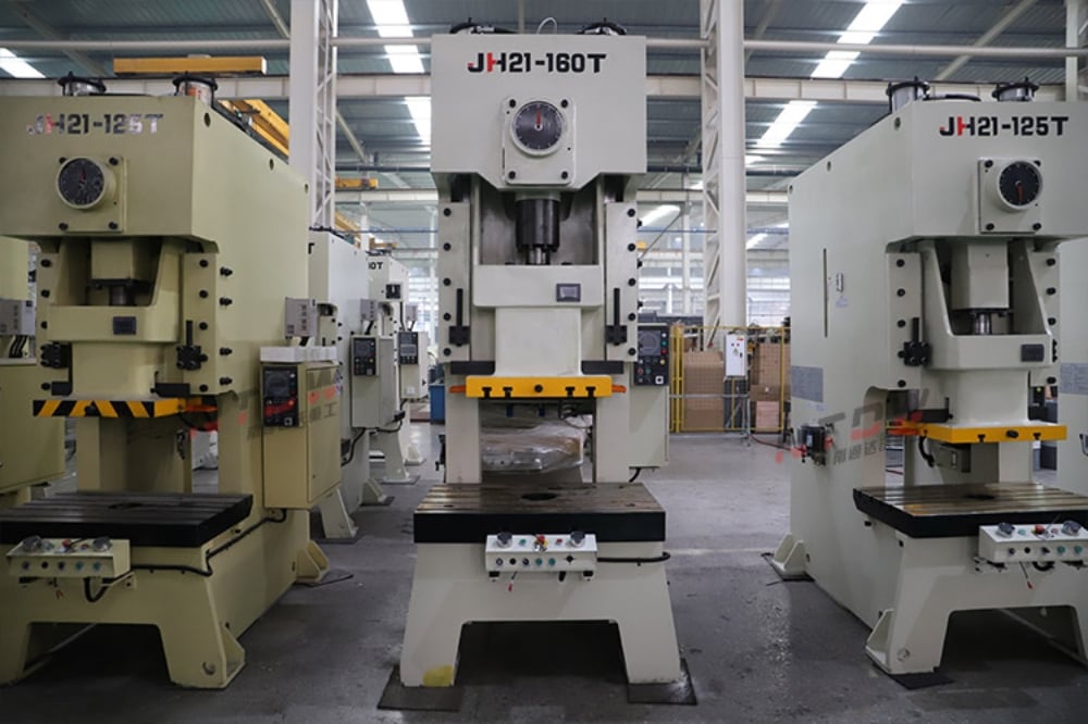
Furthermore, the technical setup involves more than just the machine itself; it encompasses the entire environment, including the leveling of the machine on the factory floor and the temperature stability of the hydraulic fluid. A machine that is not perfectly level will experience uneven wear on its gibs and ways, eventually leading to a loss of perpendicularity in the punch stroke. This guide serves as a comprehensive roadmap for engineers and operators to master these technical nuances.
Core Parameters for Accurate Punching Setup
To achieve accurate production, several core parameters must be meticulously managed during the setup phase. The first and perhaps most critical is the Shut Height. This is the distance between the bottom of the ram and the top of the bolster plate when the ram is at the bottom of its stroke. Incorrect shut height can lead to ‘bottoming out’ the tool, which can shatter the punch or damage the machine’s crankshaft and bearings. Calibration of the shut height must account for the thickness of the die set and any spacers used.
The second parameter is Die Clearance. This is the space between the punch and the die, usually expressed as a percentage of the material thickness. Proper clearance is vital for ensuring that the fracture lines from the top and bottom of the material meet correctly. If the clearance is too tight, it increases the required tonnage and accelerates tool wear; if it is too loose, it creates large burrs and a distorted hole profile. Setup professionals must select the clearance based on the material’s shear strength and thickness.
Thirdly, Stroke Length and Speed (SPM) play a significant role in production quality. While high speeds (Strokes Per Minute) increase throughput, they also generate more heat and vibration. Calibration of the stroke involves ensuring that the ram travels exactly the distance required to penetrate the material and clear the slug without unnecessary over-travel. In CNC machines, this is often managed through software, but the physical limits must be verified during the initial setup.
Lastly, Stripping Force must be considered. This is the force required to pull the punch back out of the material after the hole is made. If the stripping mechanism (usually springs or hydraulic cylinders) is not properly calibrated, the material may lift with the punch, causing deformation or ‘slug pulling,’ where the waste material is sucked back up into the die. Ensuring the stripping pressure is balanced with the punching force is a hallmark of a professional setup.
Calculation Method for Punching Force and Clearance
Accurate production relies on mathematical precision rather than guesswork. The most fundamental calculation in punching is determining the Punching Force (Tonnage) required for a specific job. The formula is generally expressed as:
P = L × t × τ
- P: Punching Force (in Newtons or Tons)
- L: Perimeter of the hole (for a round hole, L = π × d)
- t: Material thickness
- τ: Shear strength of the material (usually about 80% of the Tensile Strength)
For example, if you are punching a 20mm diameter hole in 3mm thick mild steel with a shear strength of 345 MPa, the calculation would involve finding the circumference (62.83mm), multiplying by the thickness (3mm), and then by the shear strength. It is standard practice to add a 15-20% safety margin to this result to account for tool dulling and machine friction.
Another critical calculation is the Die Clearance. For most standard applications, the total clearance (the difference between the die diameter and the punch diameter) is calculated as a percentage of the material thickness (t). For mild steel, 10% to 15% of ‘t’ is common, while for stainless steel, which is tougher and work-hardens, 15% to 20% may be required. Accurate calibration involves using feeler gauges or precision measuring tools to verify that this clearance is uniform around the entire perimeter of the punch.
Finally, operators must calculate the Press Capacity at the Point of Impact. In mechanical presses, the available tonnage varies depending on where the ram is in its stroke. The rated tonnage is usually only available near the bottom of the stroke. If the material is too thick and the punch contacts it too high in the stroke, the machine may stall or suffer structural damage. Calibration of the feed timing and ram position ensures the impact occurs within the machine’s safe energy zone.
Punching Parameter Reference Table
The following table provides a general guideline for die clearance and tonnage factors based on common industrial materials. Note that these values should be adjusted based on specific alloy grades and tool coatings.
| Material Type | Thickness (mm) | Recommended Clearance (% of t) | Shear Strength (N/mm²) | Tonnage Factor (Relative) |
|---|---|---|---|---|
| Aluminum (Soft) | 1.0 – 3.0 | 5% – 8% | 70 – 150 | 0.4 |
| Mild Steel (Q235) | 1.0 – 6.0 | 10% – 12% | 345 – 450 | 1.0 |
| Stainless Steel (304) | 1.0 – 4.0 | 15% – 18% | 520 – 600 | 1.4 |
| Copper (Half-Hard) | 1.0 – 5.0 | 8% – 10% | 200 – 280 | 0.6 |
| High-Strength Steel | 2.0 – 8.0 | 18% – 22% | 600 – 800 | 1.8 |
Using this table as a starting point, setup technicians can fine-tune their calibration. For instance, if a burr is observed on the bottom of a stainless steel part, increasing the clearance slightly within the recommended range often solves the issue without needing to regrind the tools.
Common Engineering Mistakes in Setup and Calibration
One of the most frequent mistakes in punching machine setup is Neglecting Tool Alignment. Even if the machine is perfectly calibrated, if the punch and die are not centered relative to each other, the tool will experience ‘side loading.’ This causes one side of the punch to dull prematurely and can even lead to the punch chipping or breaking. Operators should always use alignment pins or optical alignment tools during the setup of a new die set.
Another common error is Ignoring the Importance of Lubrication. Many operators view lubrication as an afterthought, but in high-speed punching, it is a critical component of the setup. Without proper lubrication, the material can gall (weld itself) to the punch tip, leading to increased stripping force and poor surface finish. Calibration of the automatic lubrication system—ensuring the nozzles are aimed correctly and the flow rate is sufficient—is a vital step that is often skipped.
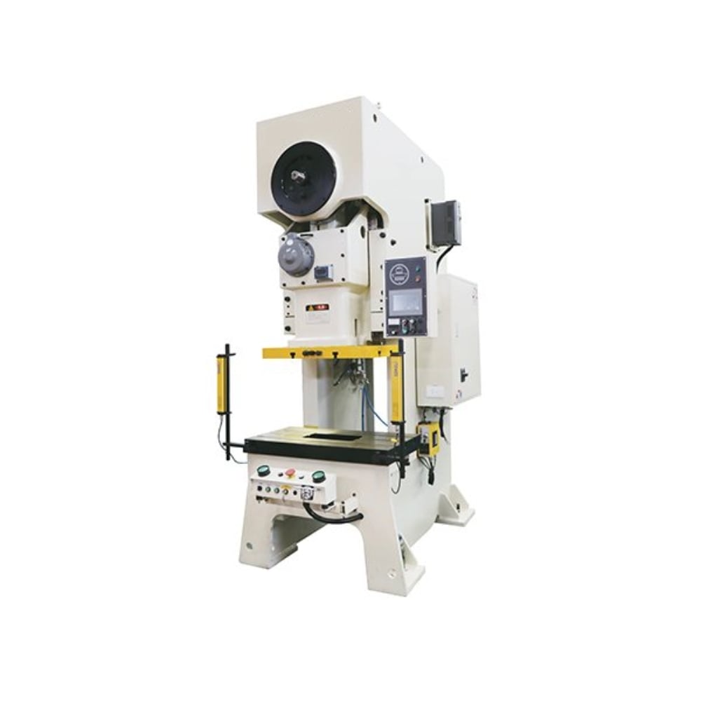
Improper Shut Height Adjustment is a mistake that can have catastrophic consequences. Some operators adjust the shut height ‘by eye’ or based on previous settings without accounting for tool sharpening. When a punch is sharpened, its length decreases, requiring an adjustment in the shut height. Failing to account for this 0.5mm or 1.0mm difference can result in incomplete holes or, conversely, excessive penetration that damages the die land.
Finally, many shops fail to perform Regular Leveling Checks. Over time, the vibrations from punching can cause a machine to shift or settle into the floor. A machine that is out of level will develop uneven stresses in its frame, leading to ‘yaw’ or ‘pitch’ during the stroke. This subtle misalignment is often the hidden cause of inconsistent part dimensions that calibration of the CNC controller cannot fix.
Selection Checklist for Punching Machine Setup
When preparing for a new production run or selecting a new punching machine like those offered by HARSLE, use the following checklist to ensure all setup and calibration bases are covered:
- Frame Integrity: Inspect the machine frame for any signs of stress cracks or loose foundation bolts. Ensure the machine is level within ±0.05mm per meter.
- Tooling Condition: Verify that punches and dies are sharp. Check for ‘pickup’ or galling on the punch flanks. Ensure the die land is sufficient for the material thickness.
- Clearance Verification: Confirm that the die clearance matches the material type and thickness according to the engineering specifications.
- Ram Parallelism: Use a dial indicator to check that the ram face is parallel to the bolster plate throughout the entire stroke.
- Safety Systems: Calibrate light curtains, emergency stops, and interlocks. A safe machine is a prerequisite for an accurate machine.
- CNC Parameters: Ensure the controller’s ‘backgauge’ offsets are calibrated. Run a test piece and measure the hole coordinates with a CMM or calibrated caliper.
- Slug Management: Check that the slug evacuation path is clear and that vacuum or air-blast systems are functioning to prevent slug pulling.
- Lubrication System: Verify the type of lubricant is appropriate for the material (e.g., vanishing oil for aluminum vs. heavy-duty EP oil for stainless).
Frequently Asked Questions (FAQ)
1. How often should I calibrate my punching machine?
Basic calibration, such as checking tool alignment and shut height, should be done at every tool change. A comprehensive machine calibration, including leveling and ram parallelism checks, should be performed every six months or after any significant ‘crash’ or overload event.
2. What causes ‘slug pulling’ and how can I fix it during setup?
Slug pulling occurs when the waste material sticks to the punch and is pulled out of the die. This is often caused by excessive vacuum, improper clearance, or lack of lubrication. During setup, you can use ‘slug-hugger’ dies or punches with urethane ejector pins to ensure the slug remains in the scrap bin.
3. Can I use the same clearance for all materials of the same thickness?
No. Different materials have different ductilities and shear strengths. For example, aluminum requires a tighter clearance to prevent excessive burrs, while stainless steel requires a larger clearance to allow the material to fracture cleanly without putting excessive strain on the punch.
4. How does heat affect punching accuracy?
Continuous high-speed punching generates heat in both the tools and the machine’s hydraulic system. Heat causes thermal expansion; a punch can grow in length by several microns, potentially changing the effective shut height. Ensuring a stable operating temperature through cooling systems is key to long-run accuracy.
5. Why is my machine making a loud ‘bang’ during the stroke?
A loud, sharp noise often indicates ‘breakthrough shock.’ This happens when the stored energy in the machine frame is released suddenly as the material shears. This can be mitigated during setup by using ‘sheared’ or ‘angled’ punches, which enter the material gradually rather than all at once.
6. What is the role of the backgauge in punching calibration?
The backgauge determines the position of the holes relative to the edges of the sheet. Calibration involves ‘homing’ the backgauge and verifying its position using a master template. If the backgauge is not calibrated, the holes will be accurate to each other but incorrectly positioned on the part.
By following these best practices for setup and calibration, manufacturers can maximize the lifespan of their HARSLE punching machines and ensure that every part meets the highest standards of precision. Accurate production is a discipline that combines technical knowledge with a rigorous attention to detail.