How to Improve Hole Quality with a Punching Machine in Metal Fabrication: A Comprehensive Technical Guide


Technical Overview of the Punching Process
In the realm of industrial manufacturing, the ability to improve hole quality a punching machine in metal fabrication is a cornerstone of operational excellence. Punching is not merely a process of forcing a tool through a sheet of metal; it is a complex mechanical interaction involving elastic deformation, plastic flow, and controlled fracture. When a punch hits the material, the metal initially deforms elastically. As the pressure increases, the material enters a plastic state, where it begins to flow into the die. Finally, the stress exceeds the material’s ultimate tensile strength, resulting in a fracture that completes the hole.
A high-quality hole is characterized by four distinct zones: the rollover, the burnish (or shear) zone, the fracture zone, and the burr. The rollover is the rounded top edge where the material was pulled down. The burnish zone is the smooth, vertical part of the hole created by the punch’s cutting edge. The fracture zone is the rougher area where the metal snapped away, and the burr is the slight protrusion at the bottom exit of the hole. To improve hole quality a punching machine in metal fabrication, an engineer must balance these zones to minimize the burr and maximize the burnish area.
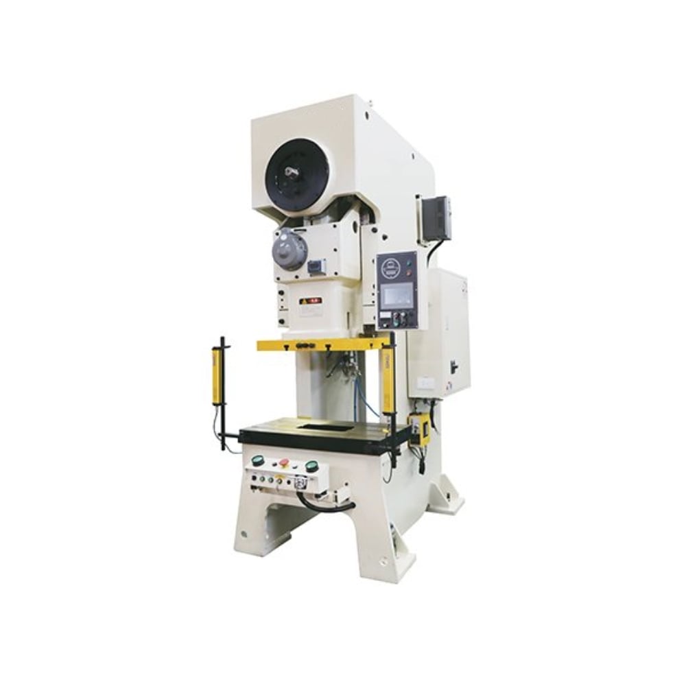
The physics of the process are heavily influenced by the speed of the punch and the rigidity of the machine frame. A high-speed CNC punching machine reduces the time the material spends in the plastic deformation phase, which can lead to cleaner fractures. However, without proper dampening and frame rigidity, high speeds can introduce vibrations that degrade hole concentricity. Therefore, understanding the mechanical limits of your equipment is the first step toward achieving superior fabrication results.
Core Parameters Influencing Hole Quality
To effectively improve hole quality a punching machine in metal fabrication, operators must master several critical parameters. The most significant of these is die clearance—the space between the punch and the die. If the clearance is too tight, the fracture lines from the top and bottom do not meet, causing a secondary shear and excessive tool wear. If the clearance is too large, the material is pulled too far into the die, resulting in a large rollover and a heavy burr.
Another vital parameter is tool sharpness. A dull punch increases the force required to penetrate the material, which leads to greater heat generation and larger burrs. Regular sharpening schedules are essential. Furthermore, the stripping force—the pressure applied to hold the sheet flat as the punch retracts—plays a major role. Insufficient stripping force can cause the material to lift or ‘oil-can,’ leading to distorted holes and potential machine jams.
Lubrication is often overlooked but is essential for maintaining hole quality. Proper lubrication reduces friction between the punch and the workpiece, which prevents ‘galling’ (the welding of small metal particles to the tool). Galling changes the effective diameter of the punch and creates scratches on the internal surface of the hole. Using a high-quality vanishing oil or a dedicated punching lubricant can significantly extend tool life and improve the aesthetic finish of the fabricated parts.
Calculation Method for Optimal Die Clearance
Determining the correct die clearance is a mathematical necessity to improve hole quality a punching machine in metal fabrication. The standard formula for total clearance (the difference between the die diameter and the punch diameter) is usually expressed as a percentage of the material thickness (T). The formula is: Clearance = T × k, where k is a constant based on the material type and its tensile strength.
For mild steel, the k factor typically ranges from 15% to 20%. For stainless steel, which is harder and work-hardens quickly, the clearance should be increased to 20% to 25% to prevent excessive tool wear. Conversely, for softer materials like aluminum, a clearance of 10% to 15% is often sufficient. It is important to note that these percentages refer to the total clearance (the sum of the clearance on both sides of the punch).
When calculating for high-precision applications, engineers might use ‘tight’ clearance (around 10%) to maximize the burnish zone, though this comes at the cost of increased tonnage and faster tool dulling. For heavy-duty industrial applications where speed and tool longevity are prioritized over a mirror-finish hole, a ‘large’ clearance (up to 30%) might be employed. Always consult the material’s technical data sheet to adjust the k factor based on its specific shear strength.
Recommended Parameter Table for Different Materials
The following table provides a baseline for setting up your punching machine to achieve optimal hole quality across various common industrial materials. These values are intended as a starting point and should be refined based on specific machine performance and tool geometry.
| Material Type | Thickness (mm) | Recommended Total Clearance (%) | Expected Burnish Zone (%) | Lubrication Requirement |
|---|---|---|---|---|
| Mild Steel (A36) | 1.5 – 3.0 | 15% – 18% | 30% – 40% | Moderate |
| Stainless Steel (304) | 1.0 – 2.5 | 20% – 25% | 20% – 30% | High (Heavy Duty Oil) |
| Aluminum (6061) | 1.0 – 5.0 | 10% – 12% | 50% – 60% | Low (Vanishing Oil) |
| Galvanized Steel | 0.8 – 2.0 | 15% – 20% | 30% – 35% | Moderate |
| Copper / Brass | 0.5 – 3.0 | 8% – 12% | 55% – 70% | Low |
Using this table helps operators quickly configure their CNC settings. For instance, if you are punching 2mm thick Stainless Steel, a 20% clearance means the die should be 0.4mm larger than the punch. Adhering to these standards is the most reliable way to improve hole quality a punching machine in metal fabrication consistently across different production runs.
Common Engineering Mistakes in Punching Operations
One of the most frequent mistakes that prevents manufacturers from being able to improve hole quality a punching machine in metal fabrication is the neglect of tool alignment. Even with the perfect clearance, if the punch is not perfectly centered within the die, one side of the hole will have an excessive burr while the other side suffers from secondary shear. This misalignment is often caused by worn turret bushings or debris in the tool holders.
Another common error is ‘slug pulling.’ This occurs when the waste material (the slug) sticks to the face of the punch and is pulled back up out of the die. This can damage the workpiece on the next hit or even break the punch. To prevent this, engineers should use ‘slug-hugger’ dies or punches with urethane ejectors. Ignoring slug management is a leading cause of downtime and poor surface quality in automated punching environments.
Furthermore, many shops fail to account for the ‘tonnage limit’ of their tools. Every punch and die set has a maximum pressure it can withstand. Punching holes that are too small relative to the material thickness (e.g., a 2mm hole in 4mm stainless steel) puts immense stress on the punch tip, leading to rapid deformation and poor hole geometry. A general rule of thumb is that the hole diameter should never be less than the material thickness for steel, and at least 1.5 times the thickness for stainless steel.
Selection Checklist for Punching Equipment and Tooling
Choosing the right machinery is fundamental to long-term quality. When looking to improve hole quality a punching machine in metal fabrication, use the following checklist during your procurement process:
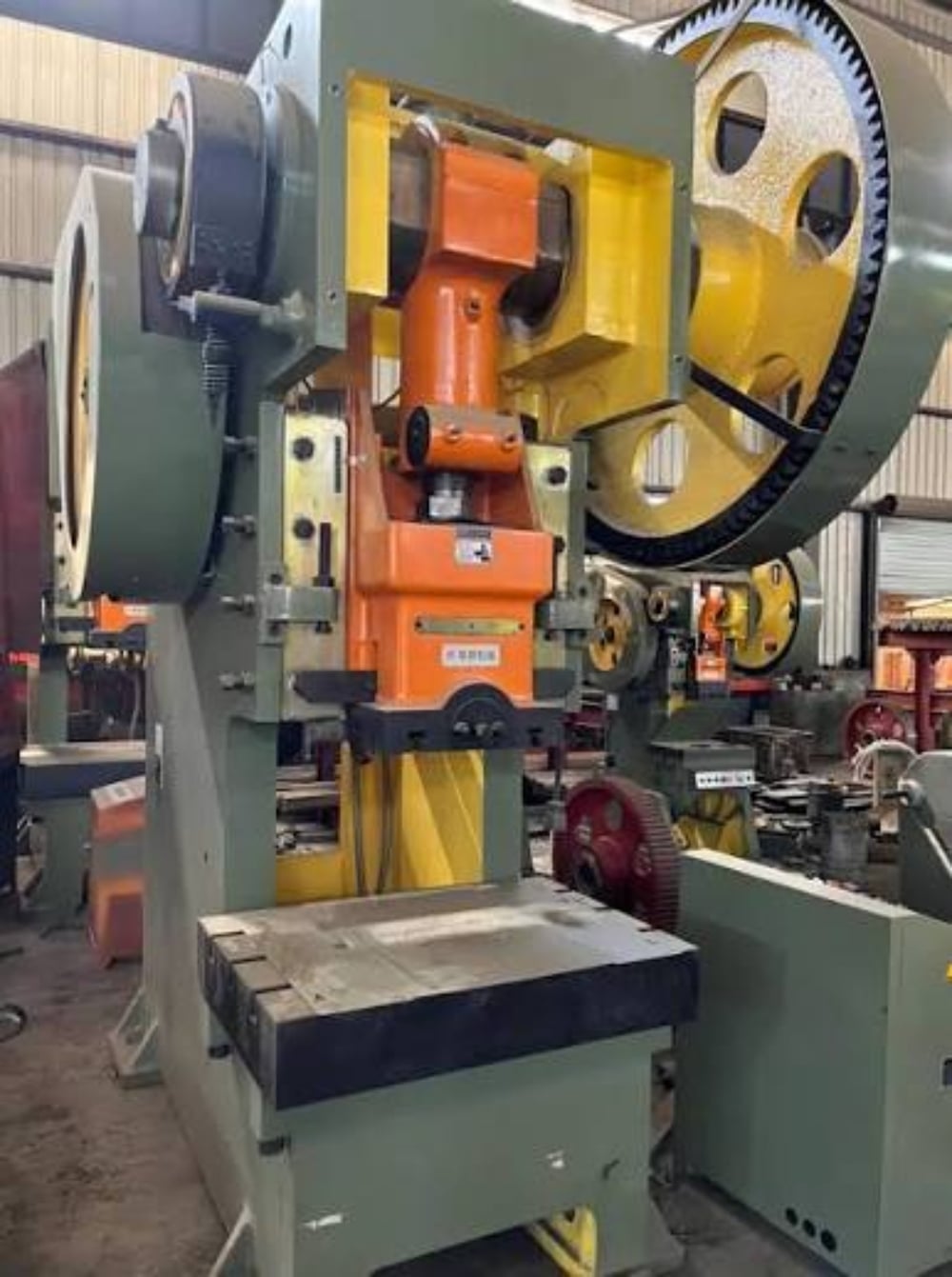
- Frame Rigidity: Does the machine utilize a closed O-frame or a reinforced C-frame? O-frames generally offer better resistance to deflection, ensuring better tool alignment during high-tonnage hits.
- CNC Precision: Check the positioning accuracy and repeatability. For high-quality holes, a repeatability of ±0.05mm or better is recommended.
- Tooling Style: Decide between Thick Turret and Thin Turret systems. Thick Turret tooling generally offers better guidance and longer life for heavy-duty applications.
- Auto-Index Stations: Ensure the machine has auto-index capabilities, which allow tools to rotate to any angle, reducing the number of tools needed and improving the flexibility of hole orientations.
- Hydraulic vs. Servo-Electric: Servo-electric punching machines offer more precise control over the punch stroke, allowing for ‘soft punching’ which reduces noise and improves the quality of the fracture zone.
- Maintenance Access: Is it easy to clean the turret and lubricate the moving parts? A clean machine is a precise machine.
Advanced Techniques: Tool Coatings and Heat Management
To push the boundaries of what is possible and further improve hole quality a punching machine in metal fabrication, consider the use of advanced tool coatings. Titanium Nitride (TiN) or Titanium Carbonitride (TiCN) coatings can significantly reduce the coefficient of friction. This results in less heat buildup during high-speed punching, which is particularly beneficial when working with gummy materials like aluminum or high-strength alloys like stainless steel.
Heat management is also critical. During long production runs, the punch can expand due to thermal buildup, slightly changing the clearance and affecting hole dimensions. Implementing a pulsed air-oil cooling system that sprays a fine mist directly onto the tool can stabilize temperatures. This ensures that the first hole of the day is identical in quality to the ten-thousandth hole, maintaining the tight tolerances required in industries like aerospace and medical device manufacturing.
Frequently Asked Questions (FAQ)
How often should I sharpen my punching tools?
Tool sharpening frequency depends on the material being punched. As a rule of thumb, tools should be inspected every 50,000 hits in mild steel or every 10,000 hits in stainless steel. Sharpening early and often (removing only 0.1mm to 0.2mm) is much better for hole quality than waiting until the tool is severely rounded.
What causes a ‘double break’ in a punched hole?
A double break, or secondary shear, is almost always caused by insufficient die clearance. When the clearance is too tight, the fracture lines from the punch and the die do not meet, forcing the material to shear a second time. This creates a jagged, poor-quality hole and doubles the wear on your machine.
Can I punch holes smaller than the material thickness?
While possible with specialized heavy-duty tooling and coatings, it is generally discouraged. Punching a hole with a diameter smaller than the thickness (e.g., a 3mm hole in 5mm plate) often leads to punch breakage. If such a hole is required, drilling or laser cutting is usually a more cost-effective and higher-quality alternative.
How does ‘slug pulling’ affect hole quality?
Slug pulling occurs when the waste metal sticks to the punch. If the slug is not cleared, the next hit will press the old slug into the new hole, causing severe deformation, tool damage, and potentially ruining the entire workpiece. Using vacuum dies or slug-ejector punches is the best way to improve hole quality a punching machine in metal fabrication by eliminating this risk.
Does the punch speed affect the burr height?
Yes. Generally, a faster punch speed results in a cleaner fracture and a smaller burr. However, if the speed is too high for the material’s ductility, it can cause micro-cracking around the hole edge. Modern CNC machines allow you to program the ram speed to find the ‘sweet spot’ for each specific material type.
Why is my hole not perfectly round?
Non-round holes are usually a sign of machine deflection or tool misalignment. If the turret is not perfectly aligned with the die base, the punch will enter the die at an angle, creating an elliptical or distorted hole. Regular calibration of the machine’s X and Y axes, along with turret alignment checks, is necessary to maintain precision.