Punching Machine Tooling Guide: Punch, Die, and Clearance Selection


Technical Overview of Punching Machine Tooling
In the realm of industrial metal fabrication, the efficiency and precision of a punching machine are heavily dictated by the quality and configuration of its tooling. Punching machine tooling is not merely a set of consumables; it is a sophisticated engineering system designed to withstand immense pressure while maintaining dimensional accuracy. At HARSLE, we recognize that understanding the synergy between the punch, the die, and the clearance is fundamental to achieving high-quality output and extending the lifespan of your machinery.
The punching process involves a punch (the male component) being forced through a workpiece into a die (the female component). While this may seem straightforward, the physics involved include elastic deformation, plastic flow, and eventual fracture. The quality of the resulting hole—characterized by its burnish, break, and burr—is a direct result of how well the tooling parameters are matched to the material properties of the workpiece. High-performance tooling must manage heat dissipation, resist wear, and prevent slug pulling, all while operating at high speeds.
Modern punching machine tooling has evolved to include specialized materials and coatings. From high-speed steel (HSS) to premium powder metallurgy steels, the choice of material impacts the tool’s toughness and hardness. Furthermore, the geometry of the tool face, such as flat-top vs. shear-angle designs, plays a critical role in reducing the tonnage required for a specific operation. This technical overview sets the stage for a deeper dive into the specific parameters that define successful punching operations.
The Role of Tooling in Machine Longevity
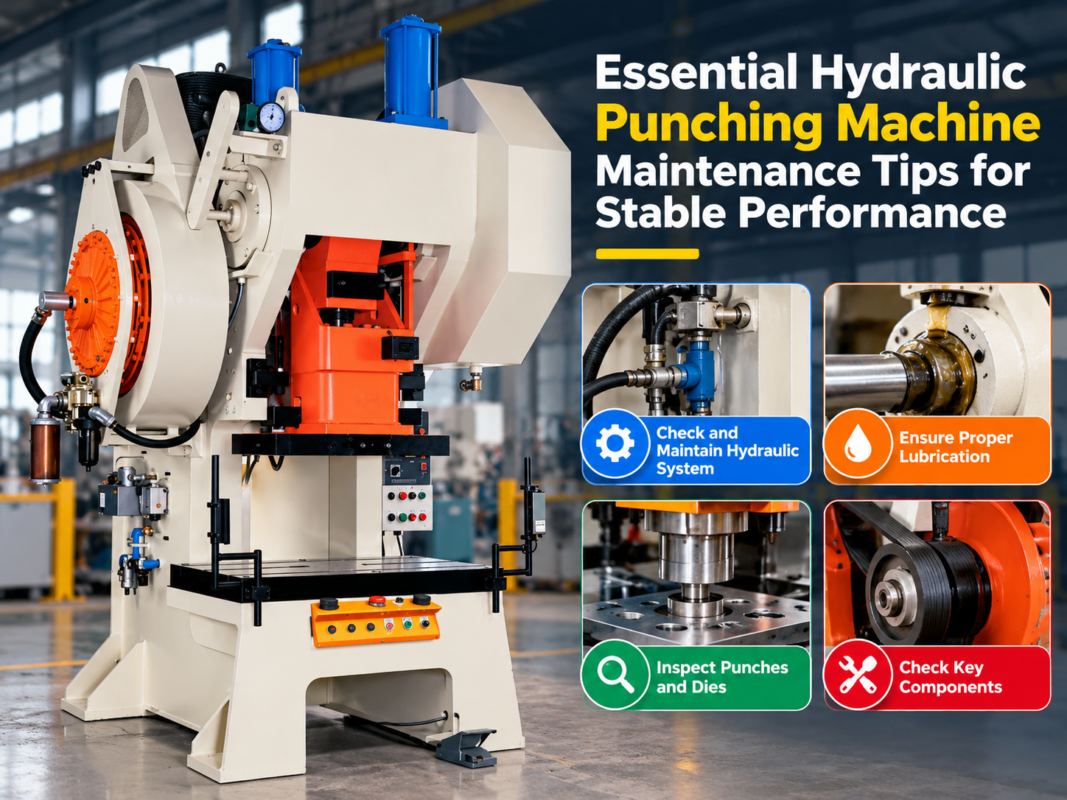
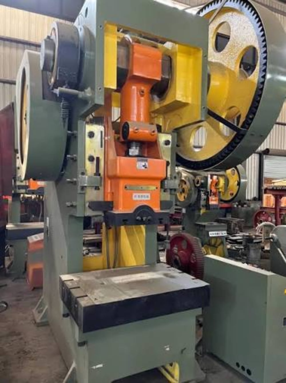
Using the correct tooling does more than just produce a clean hole; it protects the punching machine itself. Improperly selected tools or incorrect clearances can lead to excessive vibration, hydraulic shock, and premature wear on the machine’s drive system. By optimizing the tooling selection, operators can reduce the stress on the frame and the motor, leading to lower maintenance costs and a higher return on investment for the equipment.
Core Parameters: Understanding the Punch and Die
The punch and die are the primary actors in the metal-cutting drama. The punch is the component that makes contact with the upper surface of the material. Its primary characteristics include the shank, the head, and the cutting face. The cutting face can be ground in various ways to influence the punching force. For instance, a ‘roof-top’ shear or a ‘concave’ shear can significantly reduce the peak tonnage required, which is essential when working with thicker materials or high-strength alloys.
The die, on the other hand, provides the support and the opening through which the material is pushed. A critical aspect of die design is the ‘land’ and the ‘relief.’ The land is the straight portion of the die opening that determines the size of the hole, while the relief is the tapered section below the land that allows the slug to fall away freely. If the relief is too narrow, slugs can become trapped, leading to ‘slug pulling’ or even tool breakage.
Material Selection for Tooling
Tooling materials are generally categorized by their ability to resist wear and impact. D2 tool steel is a common choice for standard applications due to its high carbon and chromium content, providing excellent wear resistance. However, for high-speed applications or tougher materials like stainless steel, M2 high-speed steel or specialized powder metallurgy (PM) steels are preferred. PM steels offer a more uniform carbide distribution, which enhances both toughness and grindability, making them ideal for complex punch shapes.
Surface Treatments and Coatings
To further enhance performance, many punches and dies are treated with specialized coatings. Titanium Nitride (TiN) is a popular choice for general-purpose punching, providing a hard surface that reduces friction. For more demanding applications, Titanium Carbonitride (TiCN) or Aluminum Titanium Nitride (AlTiN) may be used. These coatings help in dissipating heat and preventing ‘galling’—a condition where the workpiece material welds itself to the tool surface due to extreme pressure and heat.
The Science of Clearance Selection
Clearance is perhaps the most misunderstood yet vital parameter in punching machine tooling. It is defined as the total difference between the size of the punch and the size of the die. For example, if you are punching a 10mm hole and the die opening is 10.2mm, the total clearance is 0.2mm. This is often expressed as a percentage of the material thickness (T).
The ‘ideal’ clearance is the one that allows the fracture lines from the top (punch side) and the bottom (die side) to meet perfectly. When the clearance is correct, the resulting hole has a clean burnished zone and a consistent fracture zone with minimal burr. If the clearance is too tight, the fracture lines do not meet, forcing the material to undergo a secondary shear, which increases the required tonnage and accelerates tool wear. Conversely, if the clearance is too large, the material is pulled into the die, resulting in a large burr and a distorted hole edge.
Factors Influencing Clearance
Several factors dictate the required clearance, including material type, material thickness, and the desired hole quality. Harder materials like stainless steel require a larger clearance (typically 15-20% of thickness) to allow for proper fracture. Softer materials like aluminum or mild steel may require a tighter clearance (8-12% of thickness) to prevent excessive rollover at the hole edge. Additionally, as the material thickness increases, the clearance must also increase proportionally to accommodate the larger volume of displaced metal.

Calculation Method for Precision Punching
To achieve optimal results, engineers must calculate both the clearance and the required punching force (tonnage). The standard formula for clearance is: C = T × k, where C is the total clearance, T is the material thickness, and k is a constant based on the material type. For mild steel, k is typically 0.10 to 0.15. For stainless steel, k increases to 0.15 to 0.20.
Calculating the punching force is equally important to ensure the machine is not overloaded. The formula for tonnage is: P = L × T × τ / 1000. In this formula, P is the force in tons, L is the perimeter of the hole (e.g., π × diameter for a round hole), T is the material thickness, and τ is the shear strength of the material (usually measured in N/mm² or MPa). It is a best practice to operate within 80% of the machine’s rated capacity to ensure longevity and safety.
Example Calculation
Suppose you need to punch a 20mm diameter hole in 3mm thick stainless steel. The shear strength of stainless steel is approximately 520 N/mm². First, calculate the perimeter: L = 20 × 3.14159 = 62.83 mm. Then, calculate the force: P = (62.83 × 3 × 520) / 1000 = 97.98 kN. To convert this to metric tons, divide by 9.81, resulting in approximately 10 tons. For clearance, using a 20% factor for stainless steel: C = 3mm × 0.20 = 0.6mm. Therefore, the die size should be 20.6mm.
Parameter Table for Tooling Clearance
The following table provides a general guideline for total clearance selection based on material type and thickness. Note that these values are percentages of the material thickness (T).
| Material Type | Recommended Clearance (% of T) | Burnish Zone (%) | Fracture Zone (%) |
|---|---|---|---|
| Mild Steel (Low Carbon) | 10% – 15% | 30% – 40% | 60% – 70% |
| Stainless Steel (304/316) | 15% – 20% | 20% – 30% | 70% – 80% |
| Aluminum (Soft) | 8% – 12% | 40% – 50% | 50% – 60% |
| Copper / Brass | 10% – 12% | 35% – 45% | 55% – 65% |
| High-Strength Steel | 20% – 25% | 15% – 25% | 75% – 85% |
It is important to remember that these are starting points. Real-world variables such as tool sharpness, machine rigidity, and lubrication can necessitate adjustments. For high-precision components, performing a test punch and inspecting the hole cross-section is the most reliable way to fine-tune the clearance.
Common Engineering Mistakes in Tooling Selection
One of the most frequent mistakes in metal punching is using the same clearance for all materials. Operators often default to a “standard” 10% clearance, which might work for mild steel but will cause rapid tool wear and excessive burrs when applied to stainless steel or heavy-gauge aluminum. This lack of adjustment leads to increased downtime for tool sharpening and higher replacement costs.
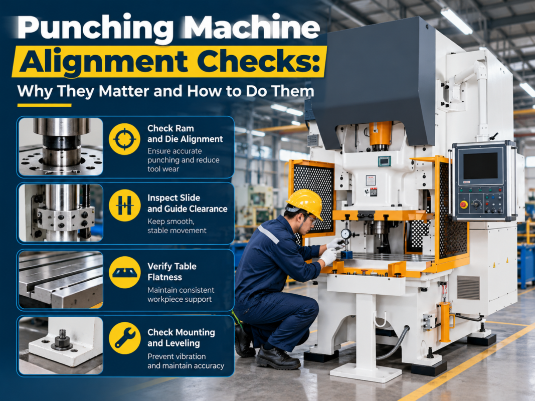
Another common error is neglecting tool alignment. Even with the perfect punch, die, and clearance, if the punch is not perfectly centered within the die, the clearance becomes uneven. This results in one side of the hole having a large burr while the other side experiences excessive friction, potentially leading to tool chipping. Regular inspection of the turret or tool holder alignment is essential for maintaining consistency.
Ignoring Slug Pulling Issues
Slug pulling occurs when the waste material (the slug) sticks to the face of the punch and is pulled back up out of the die. This can cause catastrophic damage if the slug is then deposited on top of the sheet for the next hit. Engineers often fail to specify ‘slug-hugger’ dies or vacuum systems when working with thin or oily materials. Using dies with specialized internal geometries can effectively trap the slug and prevent this issue.
Overlooking Lubrication
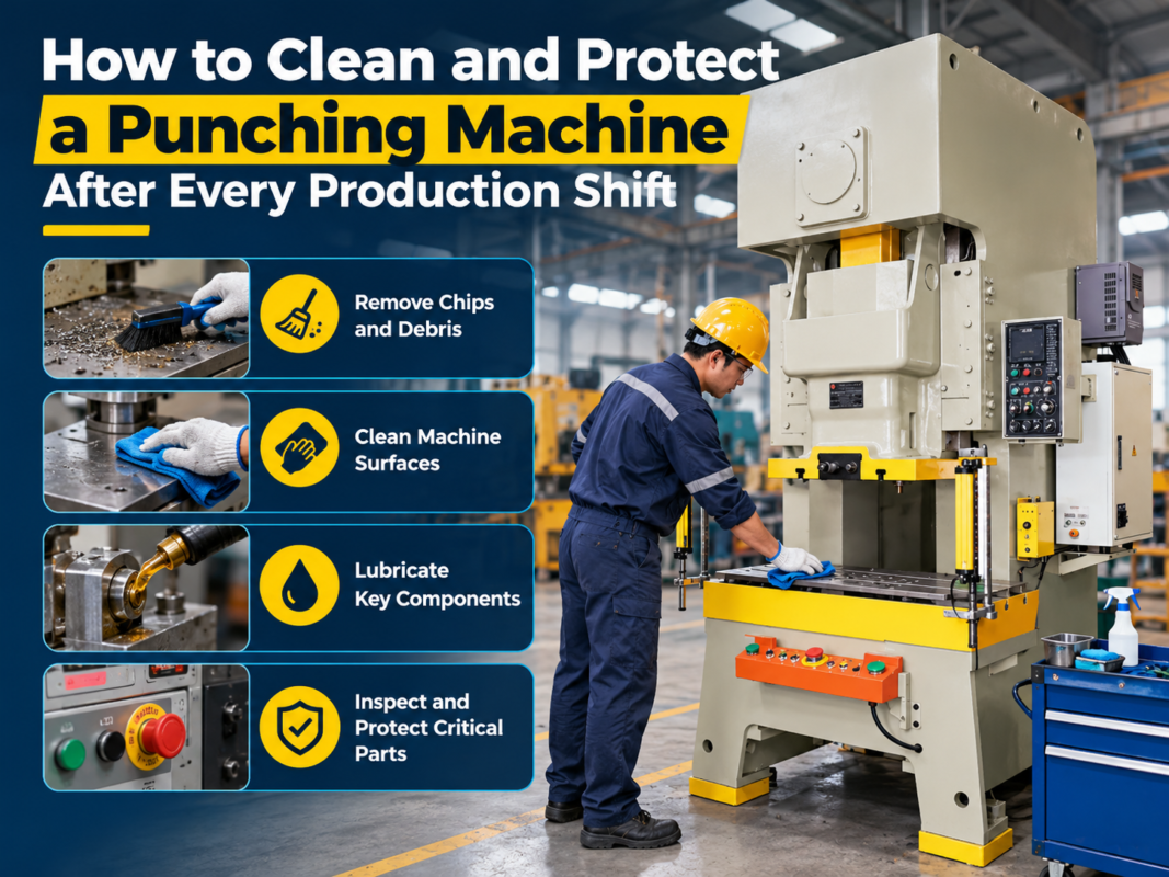
Lubrication is often treated as an afterthought, but it is critical for reducing heat and friction. Without proper lubrication, the material can gall to the punch, increasing the stripping force required to pull the punch out of the sheet. This extra force puts unnecessary strain on the machine’s stripping mechanism and can lead to sheet distortion.
Selection Checklist for Industrial Operators
When selecting tooling for your next project, follow this comprehensive checklist to ensure optimal performance and tool life:
- Identify Material Properties: Determine the tensile strength, shear strength, and thickness of the workpiece.
- Calculate Required Tonnage: Ensure the total force required does not exceed 80% of your machine’s capacity.
- Determine Optimal Clearance: Use the material-specific percentage to calculate the die opening size.
- Select Tool Material and Coating: Choose HSS or PM steels for high-volume or tough material runs; apply TiCN or AlTiN coatings for heat resistance.
- Choose Punch Face Geometry: Use shear-angled punches for thick materials to reduce noise and tonnage.
- Verify Die Relief: Ensure the die has adequate relief to prevent slug buildup.
- Inspect Alignment: Check that the punch and die are perfectly centered before starting the run.
- Implement Lubrication Strategy: Use a consistent spray or mist lubrication system suitable for the material type.
- Plan for Maintenance: Establish a sharpening schedule based on hit counts to maintain hole quality.
Frequently Asked Questions (FAQ)
1. How often should I sharpen my punching tools?
Tool sharpening frequency depends on the material being punched and the tool quality. As a rule of thumb, tools should be sharpened when the cutting edge radius reaches 0.1mm to 0.2mm. Sharpening early and often (removing only 0.05mm to 0.1mm) is much better for tool life than waiting until the tool is severely dulled.
2. What causes a large burr on the bottom of the hole?
A large burr is typically caused by excessive clearance between the punch and the die, or by a dull punch. If the clearance is correct, check the sharpness of the die and the punch. If both are sharp, try reducing the clearance slightly.
3. Can I use the same punch for different materials?
Yes, the punch determines the hole size and can be used across different materials. However, the die must be changed to provide the correct clearance for each specific material type and thickness. Using the wrong die will result in poor hole quality and tool damage.
4. What is the benefit of using a shear-angle punch?
A shear-angle punch (like a roof-top or four-way shear) enters the material gradually rather than all at once. This reduces the peak punching force (tonnage), lowers the noise level of the operation, and reduces the shock transmitted to the machine frame.
5. How do I prevent slugs from coming out of the die?
To prevent slug pulling, you can use ‘slug-free’ or ‘slug-hugger’ dies that have a slight undercut to grip the slug. Additionally, ensuring the punch has a small amount of lubricant and using a punch with a ‘slug ejector’ (a spring-loaded pin) can help push the slug away from the punch face.
6. Why is my punch chipping?
Punch chipping is often caused by excessive hardness (making the tool brittle), improper alignment, or insufficient clearance. If you are punching high-strength materials, consider switching to a tougher tool steel like M2 or a powder metallurgy grade that can better withstand the impact.