How to Reduce Burrs and Deformation in Punching Machine Operations: A Technical Guide


Technical Overview of Punching Quality Control
In the realm of high-precision metal fabrication, the quality of a punched hole is defined by its dimensional accuracy and the cleanliness of its edges. When we discuss how to reduce burrs and deformation in punching machine operations, we are essentially looking at the physics of material displacement. Punching is not merely a process of ‘cutting’ through metal; it is a high-speed sequence of elastic deformation, plastic flow, and eventual fracture. Understanding these stages is critical for any engineer or operator looking to optimize their HARSLE punching machine performance.
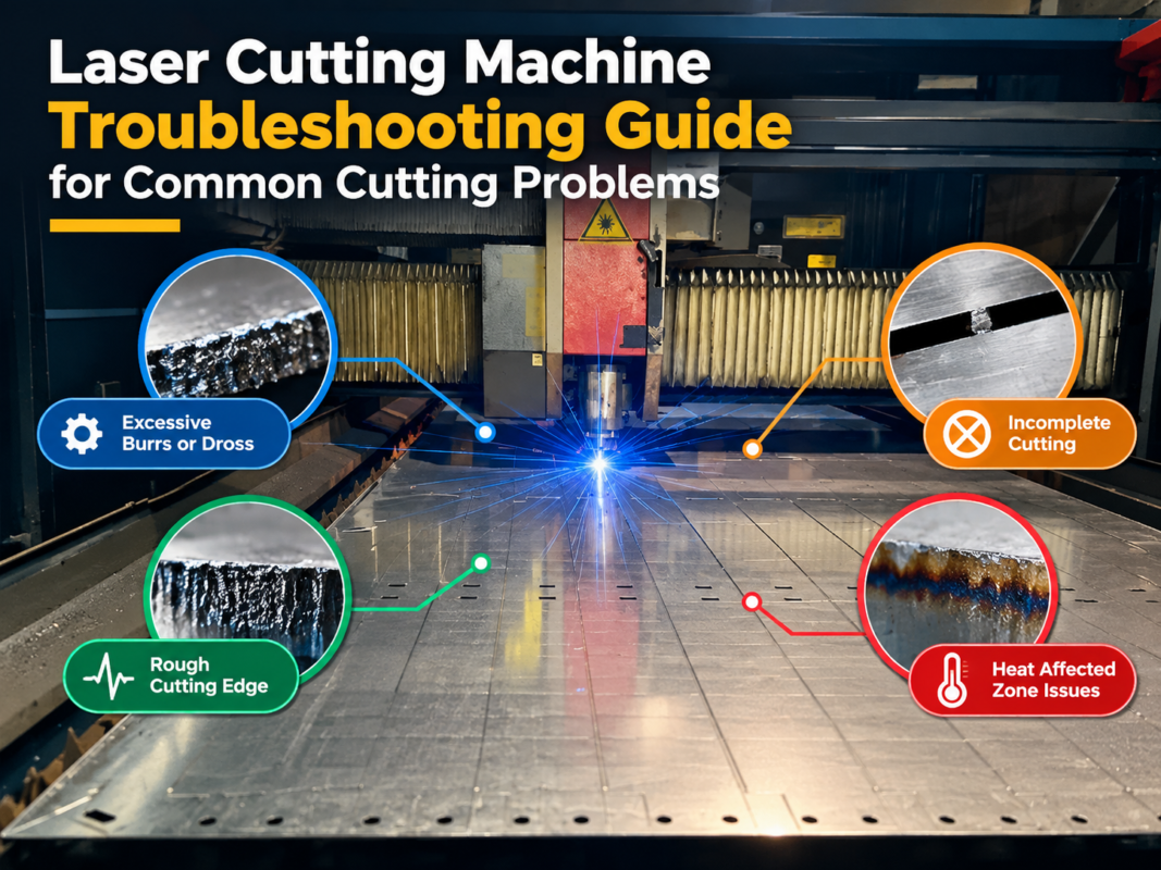
A burr is an unwanted projection of material beyond the edge of the punched hole, typically occurring on the exit side of the punch. Deformation, on the other hand, refers to the warping or ‘oil-canning’ of the sheet metal surrounding the hole. Both issues are symptoms of improper mechanical settings or tool wear. To achieve a clean shear, the fracture lines initiated from the punch edge and the die edge must meet precisely in the middle of the material thickness. If these lines do not meet, the material is forced to tear or stretch, leading to the very defects we aim to eliminate.
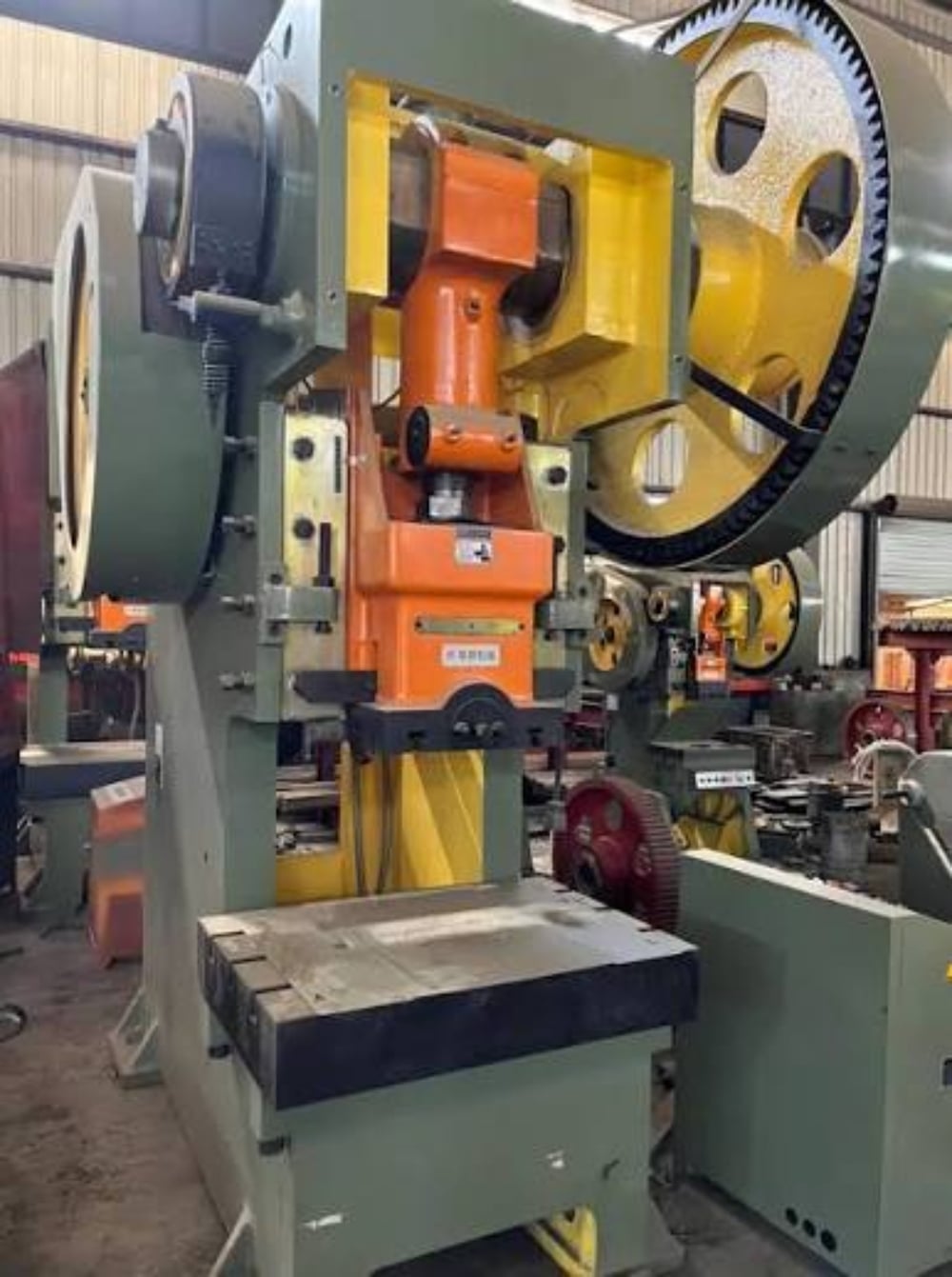
Modern CNC punching machines, such as those manufactured by HARSLE, utilize advanced hydraulic and mechanical systems to maintain extreme rigidity. However, even the best machine cannot compensate for poor tooling choices or incorrect parameter settings. Reducing burrs and deformation requires a holistic approach that considers the material properties, the geometry of the punch and die, and the dynamic forces at play during the stroke. By mastering these variables, manufacturers can significantly reduce secondary finishing costs and improve the structural integrity of their components.
Core Parameters Influencing Edge Quality
The most significant factor in determining the quality of a punched edge is the die clearance. Die clearance is the total space between the punch and the die, usually expressed as a percentage of the material thickness. If the clearance is too tight, the fracture lines will bypass each other, causing a ‘double shear’ effect which increases tool wear and creates a secondary burr. Conversely, if the clearance is too large, the material is pulled into the die before fracturing, resulting in a large rollover and a heavy burr.
Another critical parameter is the sharpness of the tooling. A dull punch acts more like a hammer than a knife, pushing the material down rather than shearing it. This increases the punching force required and leads to significant deformation around the hole. Regular inspection of the punch face and the die land is essential. Even a slight radius on the cutting edge can increase the burr height by over 100%. HARSLE recommends a strict sharpening schedule based on the number of hits and the type of material being processed.
Lubrication also plays a vital role in reducing friction and heat. During the punching process, the friction between the punch and the material generates intense heat, which can cause the material to gall or stick to the punch. This ‘slug pulling’ or material buildup alters the effective clearance and leads to inconsistent results. Using a high-quality vanishing oil or a dedicated punching lubricant ensures that the punch slides smoothly through the material and retracts without dragging the edges upward, which is a common cause of sheet deformation.
Calculation Method for Optimal Die Clearance
To effectively reduce burrs and deformation in punching machine operations, one must calculate the precise die clearance for each specific job. The general formula used in the industry is C = c × t, where C is the total clearance (the difference between the die diameter and the punch diameter), c is a constant based on the material type, and t is the material thickness.
For standard mild steel, the constant c typically ranges from 15% to 20% of the thickness for high-quality edges. For harder materials like stainless steel, the clearance must be increased (often to 20-25%) to account for the material’s higher shear strength and lower ductility. Aluminum, being softer and more prone to galling, often requires a tighter clearance (around 10-12%) to prevent the material from being drawn into the die. It is important to note that these percentages are for the *total* clearance; some manufacturers refer to ‘clearance per side,’ which would be half of these values.
When calculating for deformation control, one must also consider the ‘stripper pressure.’ The stripper plate holds the material flat against the die during the punch and retraction. If the stripper pressure is too low, the material will lift during the punch withdrawal, causing deformation. The calculation for required stripping force is generally 5% to 15% of the total punching force. Ensuring your HARSLE machine is calibrated to provide adequate clamping pressure is a prerequisite for flat, burr-free parts.
Parameter Table for Common Materials
The following table provides a reference for selecting the correct die clearance percentages to minimize burrs and deformation across various common industrial materials.
| Material Type | Thickness Range (mm) | Recommended Total Clearance (%) | Expected Edge Quality |
|---|---|---|---|
| Mild Steel (CR) | 0.5 – 3.0 | 15% – 18% | Minimal burr, smooth shear zone |
| Mild Steel (HR) | 3.0 – 6.0 | 18% – 22% | Standard industrial finish |
| Stainless Steel (304/316) | 0.5 – 4.0 | 20% – 25% | High shear, requires sharp tools |
| Aluminum (Soft) | 1.0 – 5.0 | 10% – 12% | Prevents rollover and drawing |
| Galvanized Steel | 0.5 – 2.5 | 15% – 20% | Protects zinc coating at edge |
| Copper / Brass | 0.5 – 3.0 | 12% – 16% | Clean cut, low deformation |
Note: These values are starting points. Factors such as machine age, punch speed, and specific alloy variations may require fine-tuning of these percentages by ±2%.
Common Engineering Mistakes in Punching
One of the most frequent mistakes in metal punching is the ‘one-size-fits-all’ approach to die clearance. Many shops use a standard 10% or 15% clearance for every material that comes through the door. This leads to excessive burrs on stainless steel and premature tool wear on aluminum. Each material reacts differently to the stress of punching; ignoring these metallurgical differences is a primary cause of poor part quality.
Another common error is neglecting the alignment between the punch and the die. Even with the correct clearance, if the punch is not perfectly centered within the die, the clearance will be uneven. This results in a ‘one-sided burr,’ where one side of the hole is clean and the other has a heavy flange. In CNC turret punch presses, this is often caused by worn turret bushings or misaligned tool holders. Regular calibration of the machine’s indexing stations is vital to ensure concentricity.
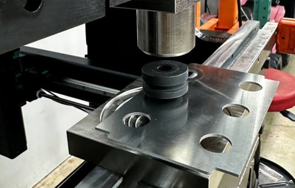
Furthermore, operators often overlook the importance of the ‘die land.’ The die land is the straight vertical section of the die before it tapers off for slug clearance. If the die land is too long, it increases friction and heat; if it is too short (due to excessive sharpening), it can lead to slug pulling. Managing the height of the die and using ‘slug-hugger’ or ‘slug-free’ die geometries can prevent slugs from coming back up and denting the next part, which is a major source of surface deformation.
Selection Checklist for Minimizing Defects
When selecting equipment or setting up a new production run, use this checklist to ensure you are optimized to reduce burrs and deformation in punching machine operations:
- Machine Rigidity: Does the machine frame (C-frame or O-frame) have the structural integrity to prevent deflection under high tonnage? HARSLE O-frame designs are preferred for high-precision work.
- Tooling Quality: Are you using high-speed steel (HSS) or premium tool steels with proper heat treatment? Cheap tooling loses its edge quickly, leading to immediate burr issues.
- Clearance Verification: Has the die clearance been calculated specifically for the current material thickness and tensile strength?
- Stripper Plate Condition: Is the stripper plate flat and free of debris? Does it provide uniform pressure around the punch?
- Lubrication System: Is the automatic lubrication system functioning, or is the operator manually applying lubricant consistently?
- Sharpening Protocol: Is there a documented log for tool hits? Are tools being sharpened before they reach a 0.1mm radius on the cutting edge?
- Slug Management: Are you using vacuum systems or specialized die geometries to ensure slugs are evacuated properly?
Frequently Asked Questions (FAQ)
Why does my punching machine produce a burr on only one side of the hole?
A one-sided burr is almost always a sign of misalignment. The punch is not entering the center of the die, causing the clearance to be too tight on one side and too loose on the other. Check your tool holders, turret alignment, and ensure the punch is seated correctly in the ram.
How does punching speed affect burr formation?
Higher speeds generally produce a cleaner break because the material has less time to flow plastically. However, excessive speed can also generate more heat. For most hydraulic HARSLE machines, the stroke speed is optimized, but adjusting the ‘hover’ height can help maintain consistent thermal conditions during high-hit-rate patterns.
Can I eliminate deformation entirely on thin sheet metal?
While difficult to eliminate entirely, you can minimize it by using ‘shear-angle’ punches (like rooftop or four-way shear). These tools enter the material at an angle, reducing the initial impact force and the total tonnage required, which significantly lowers the stress on the surrounding sheet.
What is the maximum burr height allowed in industrial standards?
While it varies by industry, a common rule of thumb is that the burr height should not exceed 10% of the material thickness. For precision electronics or aerospace parts, this requirement is often much stricter, requiring secondary deburring processes if the punching setup isn’t perfect.
How often should I sharpen my punching tools?
This depends on the material. For mild steel, you might sharpen every 50,000 to 100,000 hits. For stainless steel, you may need to sharpen every 20,000 hits. The best practice is to monitor the burr height; once it increases noticeably, it is time to sharpen. Removing just 0.1mm to 0.2mm during regular sharpening is better than waiting and having to grind off 0.5mm or more.