Industrial Punching Machine Workflow: From Sheet Loading to Finished Parts


Technical Overview of the Industrial Punching Machine Workflow
The modern industrial punching machine workflow is a sophisticated sequence of operations designed to transform raw metal sheets into precision-engineered components. At the heart of this process is the CNC turret punch press or the high-speed hydraulic punch, which utilizes a combination of mechanical force and computer-controlled precision. Understanding the Industrial Punching Machine Workflow: From Sheet Loading Finished Parts is essential for any fabrication facility looking to optimize throughput and minimize material waste. This workflow integrates mechanical engineering, software programming, and material science to achieve high-speed production with tolerances often measured in microns.
Historically, punching was a manual, labor-intensive process. However, the advent of CNC (Computer Numerical Control) technology has revolutionized the industry. Today, a HARSLE industrial punching machine operates through a seamless digital-to-physical transition. The process begins with a digital design, which is then translated into G-code that instructs the machine on every movement, tool change, and strike. The technical complexity lies in the synchronization of the X and Y axes, which move the sheet metal at high speeds, and the Z-axis, which controls the punching ram.
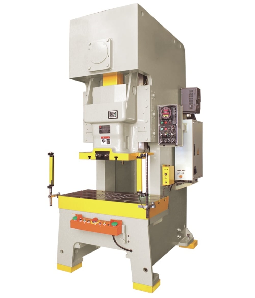
The workflow can be categorized into three primary phases: pre-processing (programming and loading), processing (the actual punching cycle), and post-processing (unloading and sorting). Each phase requires specific technical considerations. For instance, during pre-processing, the choice of nesting software can significantly impact material utilization. During the processing phase, the machine must manage heat dissipation and tool wear. Finally, post-processing ensures that the finished parts are free of burrs and ready for subsequent assembly or finishing stages.
Modern machines, such as those offered by HARSLE, often feature servo-electric or advanced hydraulic systems. Servo-electric punch presses are particularly noted for their energy efficiency and precise control over the ram’s stroke, allowing for complex forming operations like louvering, embossing, and threading within the same workflow. This multi-functionality reduces the need for secondary operations, thereby streamlining the entire production line from sheet loading to finished parts.
Phase 1: Material Preparation and Sheet Loading
The workflow begins with the selection and preparation of the raw material. Industrial punching machines typically handle a variety of metals, including cold-rolled steel, stainless steel, and aluminum. The thickness of the sheet is a critical factor, as it determines the required tonnage and the clearance between the punch and the die. Before loading, sheets must be inspected for flatness and surface contaminants that could interfere with the clamping mechanism or damage the tooling.
Sheet loading can be performed manually or through automated systems. In a manual setup, operators use vacuum lifters or magnetic grippers to position the sheet onto the machine’s brush or ball table. Precision is vital here; the sheet must be squared against the machine’s work-holders (clamps) to ensure that the CNC coordinates align perfectly with the physical material. Automated loading systems, often referred to as ‘load/unload’ cells, use robotic arms or gantry systems to pick sheets from a stack and place them onto the table, significantly increasing the duty cycle of the machine.
Phase 2: CNC Programming and Nesting
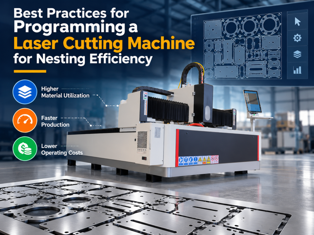
Once the material is ready, the focus shifts to the digital workflow. Engineers use CAD (Computer-Aided Design) software to create the part geometry. This file is then imported into CAM (Computer-Aided Manufacturing) software specifically designed for punching. The CAM software performs ‘nesting,’ which is the process of arranging multiple parts on a single sheet of metal to minimize scrap. Efficient nesting is a hallmark of a professional Industrial Punching Machine Workflow: From Sheet Loading Finished Parts.
The software also assigns specific tools from the machine’s turret to each feature of the part. For example, a large rectangular cutout might be created using a series of hits with a square tool (nibbling), while a small circular hole would use a single hit from a round punch. The program also defines the ‘hit sequence’ to prevent the sheet from warping due to internal stresses. Advanced software can even simulate the entire punching process to identify potential collisions between the clamps and the tools before the first hit is ever made.
Core Parameters of Industrial Punching Machines
To master the Industrial Punching Machine Workflow: From Sheet Loading Finished Parts, one must understand the core parameters that govern machine performance. These parameters dictate the limits of what can be fabricated and the speed at which the workflow can proceed. The most critical parameter is Tonnage, which refers to the maximum force the machine can exert. A 30-ton machine, for example, is standard for most sheet metal work, but thicker materials may require 50 tons or more.
Another vital parameter is the Hit Rate. This is measured in hits per minute (HPM) and varies depending on the distance between holes. For marking or closely spaced nibbling, high-end machines can exceed 1,000 HPM. Positioning Speed is also crucial; this is the speed at which the X and Y axes move the sheet. Faster positioning speeds reduce the non-productive time between hits, directly impacting the overall efficiency of the workflow. Throat Depth is the distance from the center of the punch to the back of the machine frame, determining the maximum width of the sheet that can be processed without flipping.
- Turret Capacity: The number of tool stations available. More stations mean fewer manual tool changes and more complex parts can be finished in one cycle.
- Positioning Accuracy: The precision with which the machine can locate a hole, typically within +/- 0.1mm.
- Maximum Sheet Thickness: Usually ranges from 0.5mm to 6.35mm for standard turret presses.
- Auto-Index Stations: Stations that can rotate 360 degrees, allowing a single tool to punch at any angle, which is essential for complex geometries.
Calculation Method for Punching Force
In a professional engineering environment, calculating the required punching force is non-negotiable. Overloading a machine can lead to catastrophic frame failure or tool breakage, while underestimating force can result in incomplete punches and damaged workpieces. The standard formula for calculating punching force (P) is based on the perimeter of the cut, the thickness of the material, and its shear strength.
The formula is: P = L × t × τ
Where:
P = Punching force (kN or Tons)
L = Perimeter of the hole (mm)
t = Material thickness (mm)
τ = Shear strength of the material (kN/mm² or MPa)
For example, if you are punching a 50mm diameter circular hole in a 2mm thick stainless steel sheet (shear strength approx. 0.4 kN/mm²):
L = π × D = 3.14 × 50 = 157 mm
P = 157 × 2 × 0.4 = 125.6 kN
To convert kN to Tons, divide by 9.81: 125.6 / 9.81 ≈ 12.8 Tons.
It is also important to consider the ‘Die Clearance.’ This is the space between the punch and the die. Proper clearance (typically 15-20% of material thickness) ensures a clean cut and reduces the force required. Incorrect clearance leads to excessive burrs or ‘slug pulling,’ where the waste material sticks to the punch and is pulled back up, potentially damaging the next part of the sheet.
Industrial Punching Machine Parameter Table
| Machine Type | Drive System | Max Tonnage | Max Hit Rate (HPM) | Best Application |
|---|---|---|---|---|
| Mechanical Press | Flywheel/Crank | 15 – 100T | 200 – 400 | High-volume, simple shapes |
| Hydraulic Press | Hydraulic Cylinder | 20 – 50T | 300 – 600 | Heavy-duty, variable stroke |
| Servo-Electric Press | Servo Motor | 20 – 30T | 800 – 1200 | High precision, energy efficient |
| CNC Turret Punch | Multi-Tool Turret | 30T (Standard) | 1000+ | Complex parts, nesting |
Common Engineering Mistakes in the Punching Workflow
Even with advanced machinery, errors in the Industrial Punching Machine Workflow: From Sheet Loading Finished Parts can lead to significant downtime. One of the most common mistakes is improper tool maintenance. Punching generates immense heat and friction; without regular sharpening and lubrication, tools become dull, leading to increased punching force requirements and poor edge quality. Operators should implement a ‘hit count’ tracking system to know exactly when a tool needs maintenance.
Another frequent error is incorrect clamp positioning. If the CNC program does not account for the physical location of the work-holders, the punch can strike the clamp, causing expensive damage to both the tool and the machine. Modern CAM software includes ‘dead zone’ detection to prevent this, but manual overrides or incorrect machine offsets can still lead to accidents. Furthermore, neglecting the ‘slug management’ system can cause issues. If slugs (the waste metal) are not properly vacuumed or pushed through the die, they can pile up and cause the sheet to lift or the tool to jam.
Material grain direction is often overlooked in the nesting phase. For parts that require subsequent bending, the orientation of the punch relative to the grain of the metal can affect the strength of the final part. Punching across the grain is generally preferred for parts that will be bent. Lastly, failing to account for ‘sheet deformation’ during high-density punching can lead to parts that are out of tolerance. As more holes are punched, the internal stresses in the metal can cause the sheet to bow or twist, which must be compensated for by the machine’s leveling system or by adjusting the hit sequence.
Selection Checklist for Industrial Punching Machines
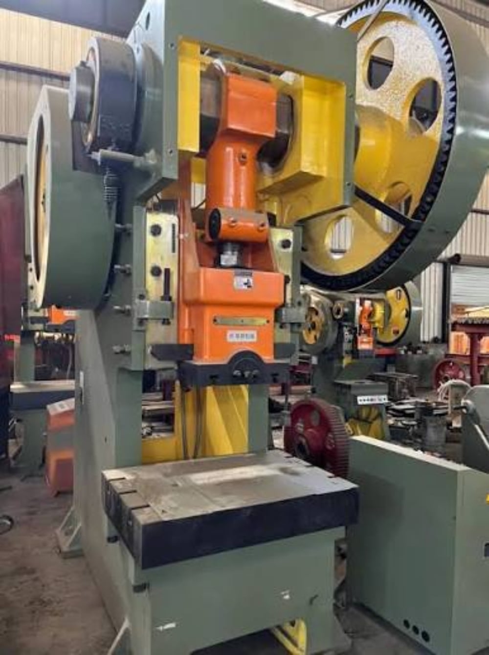
Choosing the right equipment is the foundation of an efficient Industrial Punching Machine Workflow: From Sheet Loading Finished Parts. Use the following checklist to evaluate your needs:
- Material Compatibility: Does the machine tonnage and tooling support your thickest and hardest materials (e.g., 6mm stainless steel)?
- Production Volume: For high-volume runs, look for high HPM rates and automated loading/unloading options.
- Part Complexity: Does the machine have enough turret stations and auto-index capabilities for your most complex designs?
- Software Integration: Is the machine compatible with industry-standard CAD/CAM software for seamless nesting and G-code generation?
- Energy Efficiency: Consider servo-electric models if electricity costs and environmental impact are primary concerns.
- Floor Space: Ensure the machine’s footprint, including the travel area of the sheet metal, fits within your facility layout.
- After-Sales Support: Does the manufacturer (like HARSLE) provide robust technical support, spare parts, and operator training?
Frequently Asked Questions (FAQ)
1. How often should punching tools be sharpened?
Tool life depends on the material being punched. Generally, tools should be inspected every 50,000 to 100,000 hits. Punching stainless steel will dull tools much faster than aluminum. Sharpening should remove only the minimum amount of material necessary to restore the edge.
2. What is the difference between a turret punch and a laser cutter?
A turret punch is generally faster and more cost-effective for parts with many holes, forming operations (like louvers), or repetitive shapes. A laser cutter is better for highly complex, irregular contours and thicker materials where mechanical force is impractical.
3. Can a punching machine perform bending?
While not a replacement for a press brake, many modern CNC punching machines can perform small-scale forming and bending (up to 90 degrees) using specialized ‘offset’ or ‘forming’ tools. This is a key part of an integrated Industrial Punching Machine Workflow: From Sheet Loading Finished Parts.
4. How do I prevent ‘slug pulling’?
Slug pulling occurs when the waste material sticks to the punch. This can be prevented by using ‘slug-hugger’ dies, applying proper lubrication, ensuring correct die clearance, and using vacuum systems designed to pull the slug away from the work area.
5. Is CNC programming difficult to learn?
Modern CAM software is very user-friendly, featuring graphical interfaces and automated nesting. Most operators with a basic understanding of geometry and metalworking can become proficient with a few weeks of dedicated training.
6. What maintenance does the machine itself require?
Daily maintenance includes cleaning the table (brushes or balls), checking hydraulic fluid levels (if applicable), and ensuring the lubrication system for the ram and X/Y axes is functioning. Monthly checks should include belt tension, electrical connections, and frame alignment.