CNC Press Brake Programming Guide: Steps to Improve Efficiency and Repeatability


Technical Overview of CNC Press Brake Programming
In the modern landscape of metal fabrication, the CNC (Computer Numerical Control) press brake stands as a cornerstone of precision and productivity. CNC press brake programming is the process of translating complex engineering designs into a series of machine instructions that control the movement of the ram, the positioning of the backgauge, and the application of force. For manufacturers like HARSLE, the goal of advanced programming is not just to bend metal, but to do so with absolute consistency across thousands of cycles. This technical guide explores the nuances of CNC Press Brake Programming: Steps Improve Efficiency Repeatability, ensuring that operators and engineers can maximize the potential of their equipment.
The evolution of press brake technology has moved from manual mechanical stops to sophisticated multi-axis CNC systems. Modern controllers, such as those from Delem, Cybelec, or ESA, allow for 2D and 3D graphical programming. This evolution has significantly reduced the ‘art’ required by the operator and replaced it with scientific precision. By utilizing high-resolution encoders and closed-loop hydraulic systems, CNC programming ensures that the Y1 and Y2 cylinders move in perfect synchronization, maintaining parallelism even under off-center loading conditions. Understanding these technical foundations is the first step toward achieving high-efficiency production runs.
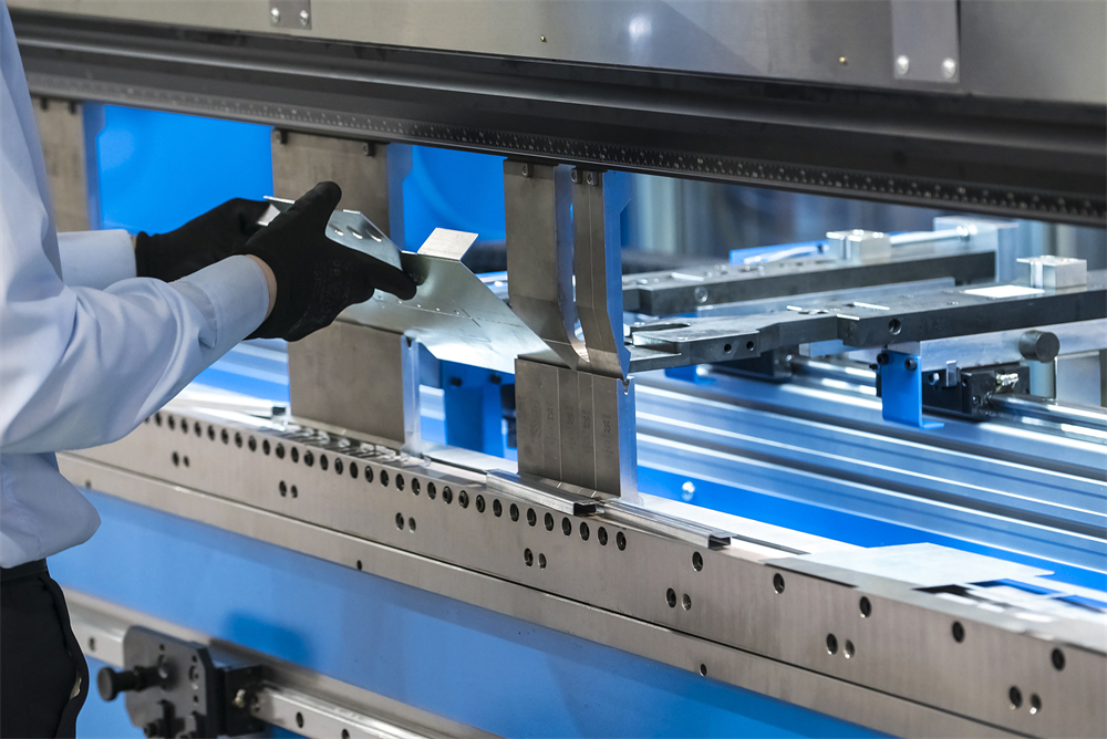
Efficiency in programming is often dictated by the software’s ability to handle complex calculations automatically. Modern CNC press brakes utilize offline programming software, which allows engineers to prepare bending sequences on a workstation while the machine is still running a previous job. This minimizes downtime and allows for collision detection before the first piece of metal is even loaded. Repeatability, on the other hand, is a function of how well the program accounts for material variables, such as springback and thickness fluctuations. A well-programmed CNC cycle includes compensation for these factors, ensuring that the first part is identical to the thousandth part.
Furthermore, the integration of Industry 4.0 features into CNC programming allows for data logging and remote diagnostics. By analyzing the data generated during each bend, manufacturers can identify patterns that lead to tool wear or hydraulic inefficiencies. This proactive approach to programming and maintenance ensures that the press brake remains a reliable asset in the production line. As we delve deeper into the core parameters and calculation methods, it becomes clear that successful programming is a blend of material science, mechanical engineering, and digital logic.
Core Parameters in CNC Press Brake Programming
To achieve the desired results in metal bending, several core parameters must be accurately defined within the CNC program. The first and most critical parameter is the material specification. This includes the material type (e.g., mild steel, stainless steel, aluminum), its thickness, and its tensile strength. Because different materials react differently under pressure, the CNC controller uses these inputs to calculate the required tonnage. For instance, stainless steel requires significantly more force to bend than aluminum of the same thickness, and it also exhibits greater springback, which must be programmed into the final angle calculation.
The second set of parameters involves the tooling selection. The programmer must input the exact dimensions of the upper punch and the lower V-die. This includes the punch radius, the die opening width (V-width), and the die angle. The relationship between the material thickness and the V-die opening is fundamental; a standard rule of thumb is to use a V-opening that is 8 times the material thickness for mild steel. Incorrect tooling data in the program will lead to inaccurate bend angles and potential damage to the machine or the tools themselves. Modern HARSLE machines often feature a tool library where these parameters are stored and easily recalled.
Backgauge positioning represents the third pillar of core parameters. In a multi-axis CNC press brake, the backgauge can move in several directions: X (depth), R (height), and Z1/Z2 (lateral position). Programming these axes correctly is essential for complex parts with multiple bends. The X-axis determines the flange length, while the R-axis ensures the gauge fingers are at the correct height to support the material, especially when using offset dies. The Z-axes allow for the positioning of the fingers to accommodate different part widths. Precise programming of these axes eliminates the need for manual measurements and significantly boosts repeatability.
Finally, crowning and pressure control are vital parameters for long-length bending. When a long sheet is bent, the machine’s frame and bed can deflect slightly under high pressure, leading to a ‘canoe effect’ where the angle in the center of the part is different from the ends. CNC programming allows for the activation of hydraulic or mechanical crowning systems that compensate for this deflection in real-time. By adjusting the pressure and the crowning compensation based on the part length and material thickness, the programmer ensures a uniform angle across the entire length of the workpiece.
Calculation Method for Precision Bending
The mathematical heart of CNC press brake programming lies in calculating the Bend Allowance (BA) and the Bend Deduction (BD). When metal is bent, the outer surface stretches and the inner surface compresses. Somewhere between these two surfaces lies the ‘neutral axis,’ which remains unchanged in length. The position of this neutral axis is defined by the K-factor. Calculating the flat length of a part requires an accurate understanding of these values to ensure that the final dimensions meet the engineering drawings.
The formula for Bend Deduction is typically expressed as: BD = 2 * (R + T) * tan(A/2) – BA, where R is the inside bend radius, T is the material thickness, and A is the bend angle. However, most modern CNC controllers simplify this by allowing the operator to input the desired final dimensions and the K-factor, and the software calculates the required flat length and backgauge positions automatically. For standard mild steel, a K-factor of 0.44 to 0.48 is commonly used, but this must be adjusted for different materials and bending methods (air bending vs. bottoming).

Another critical calculation is the required bending force, or tonnage. The formula for estimating tonnage in air bending is: P = (650 * T^2 * L) / V (for mild steel), where P is the force in tons, T is the thickness, L is the length of the bend, and V is the V-die opening. Programming the correct tonnage is essential for safety and machine longevity. If the programmed tonnage is too low, the bend will be incomplete; if it is too high, it can cause ‘coining’ of the material or even crack the die. CNC systems provide safety limits to prevent over-tonnage based on the entered tool specifications.
Advanced programming also involves calculating the ‘Springback Compensation.’ Every material has an elastic limit; when the pressure is released, the metal will slightly return toward its original shape. To achieve a 90-degree bend, the machine might actually need to bend the material to 88 or 87 degrees. High-end CNC controllers have built-in databases for springback, or they can interface with laser angle-measuring systems that measure the angle during the bend and automatically adjust the stroke depth (Y-axis) to reach the exact target angle. This closed-loop calculation is the pinnacle of repeatability in modern fabrication.
Standard Parameter Table for V-Die Selection
Choosing the correct V-die opening is a fundamental step in the programming process. The following table provides a general guideline for selecting the V-die width based on material thickness (T) for mild steel with a tensile strength of approximately 450 MPa. Note that for stainless steel, the required tonnage should be increased by approximately 50%.
| Material Thickness (mm) | Recommended V-Opening (mm) | Inside Radius (mm) | Min. Flange Length (mm) | Tonnage per Meter (Approx.) |
|---|---|---|---|---|
| 0.5 – 0.8 | 6 | 1.0 | 4.2 | 6 – 8 |
| 1.0 – 1.2 | 8 | 1.3 | 5.5 | 9 – 12 |
| 1.5 – 2.0 | 12 | 2.0 | 8.5 | 15 – 18 |
| 2.5 – 3.0 | 20 | 3.5 | 14.0 | 25 – 30 |
| 4.0 – 5.0 | 32 | 5.5 | 22.0 | 40 – 50 |
| 6.0 – 8.0 | 50 | 8.5 | 35.0 | 60 – 80 |
| 10.0 – 12.0 | 80 | 13.0 | 55.0 | 100 – 120 |
This table serves as a starting point for programmers. It is important to remember that using a smaller V-opening than recommended will increase the required tonnage significantly and may result in a sharper inside radius, which can weaken the material at the bend line. Conversely, using a larger V-opening reduces the required tonnage but increases the minimum flange length that can be accurately bent. In CNC programming, these values are often pre-loaded into the controller’s logic to suggest the best tooling for the job.
Common Engineering Mistakes in CNC Programming
One of the most frequent mistakes in CNC press brake programming is ignoring the grain direction of the metal. Sheet metal is rolled in a specific direction, and bending parallel to the grain can lead to cracking, especially in harder materials or tighter radii. A skilled programmer will orient the parts on the sheet (during the nesting phase) so that the primary bends are made across the grain. If the program does not account for this, the repeatability of the part’s structural integrity will be compromised, leading to high scrap rates.
Another common error is the failure to account for ‘Tooling Interference’ or collisions. In complex multi-bend sequences, the part may swing up and hit the upper ram or the backgauge fingers during the second or third bend. While modern 3D simulation software can detect these issues, many operators still rely on 2D programming or manual entry, which increases the risk of expensive tool damage. Always verify the bending sequence in a simulation environment to ensure that the part geometry does not interfere with the machine components at any stage of the process.
Neglecting the ‘Minimum Flange Length’ is a third mistake that affects both efficiency and safety. If a flange is too short for the selected V-die, it will not span the opening properly and will slip into the die during the bend. This results in an inaccurate angle and a potential safety hazard. Programmers must ensure that the design of the part is compatible with the available tooling. If a short flange is required, special ‘acute’ dies or ‘wing-bend’ tooling must be programmed and utilized to maintain precision.
Finally, many shops fail to update their tool libraries within the CNC controller. Over time, tools wear down, and their actual dimensions may deviate from the manufacturer’s original specs. If the program is using ‘perfect’ tool data for ‘worn’ tools, the resulting bends will be inconsistent. Regularly measuring tools and updating the CNC database is a critical step in maintaining repeatability. Furthermore, failing to program the correct ‘dwell time’ at the bottom of the stroke can lead to inconsistent springback, as the material needs a moment to ‘set’ under pressure.
Selection Checklist for High-Efficiency CNC Press Brakes
When selecting a CNC press brake to improve programming efficiency and repeatability, consider the following checklist of essential features:
- Advanced CNC Controller: Look for controllers with 15-inch or larger touchscreens, 3D graphical interfaces, and high processing speeds (e.g., Delem DA-66T or DA-69T).
- Multi-Axis Backgauge: Ensure the machine has at least 4 axes (X, R, Z1, Z2). For complex parts, 6-axis systems (X1, X2, R1, R2, Z1, Z2) provide maximum flexibility.
- Automatic Crowning System: A CNC-controlled hydraulic or mechanical crowning system is non-negotiable for maintaining accuracy over long lengths.
- Offline Programming Software: Verify that the machine comes with or is compatible with high-quality offline software to reduce setup times.
- Fast Approach and Return Speeds: High-speed hydraulics reduce cycle times, significantly boosting overall efficiency in high-volume production.
- Angle Measurement Systems: Consider integrated laser or contact angle sensors that provide real-time feedback and automatic correction.
- Tooling Compatibility: Ensure the machine uses standard high-precision tooling (like Euro-style or New Standard) that is easy to source and program.
- Safety Integration: Look for integrated laser safety guards (like DSP or LazerSafe) that allow the machine to operate at high speeds without compromising operator safety.
Frequently Asked Questions (FAQ)
1. What is the difference between Air Bending and Bottoming in CNC programming?
Air bending is the most common method in CNC programming. The material only touches the two edges of the V-die and the tip of the punch. The angle is determined by the depth of the punch (Y-axis). Bottoming involves pressing the material all the way to the bottom of the die. Air bending is more versatile as one tool set can produce many angles, whereas bottoming requires specific tools for each angle but offers higher precision for thin materials.
2. How does the K-factor affect the final part dimensions?
The K-factor represents the ratio of the neutral axis position to the material thickness. If the K-factor is incorrect in your CNC program, the calculated flat length of the part will be wrong. This means that even if your bend angles are perfect, the overall dimensions of the finished part (e.g., the total length of a U-bracket) will be out of tolerance.
3. Why is my CNC press brake not repeating the same angle?
Inconsistency is often caused by variations in material thickness or tensile strength between different batches of metal. Other factors include hydraulic oil temperature fluctuations, worn tooling, or a lack of proper crowning compensation. Using a CNC machine with an automatic angle-measuring system is the best way to solve repeatability issues caused by material variables.
4. Can I program a CNC press brake to bend multiple parts at once?
Yes, this is known as ‘Stage Bending.’ By setting up multiple tool sets along the length of the bed, you can program the CNC to move the backgauge to different positions for each tool station. This allows an operator to complete a complex part with several different bend types in a single handling, greatly improving efficiency.
5. How often should I calibrate the CNC axes?
For high-precision environments, it is recommended to check the calibration of the Y and X axes every six months. However, modern CNC systems like those from HARSLE have self-diagnostic routines and high-resolution encoders that rarely go out of calibration unless there is a mechanical collision or a major component failure.