How Automation Improves Press Brake Bending for Modern Fabrication Lines


Technical Overview: The Shift Toward Automated Bending
In the rapidly evolving landscape of industrial manufacturing, the integration of advanced technologies has redefined traditional processes. One of the most significant shifts is how automation improves press brake bending for modern fabrication lines. Historically, press brake operation was a labor-intensive task requiring highly skilled operators to manually position heavy sheets, execute bends, and manage complex sequences. Today, the introduction of robotic arms, sophisticated CNC controllers, and automated material handling systems has transformed the press brake from a standalone machine into a high-speed, high-precision production cell.
Automation in press brake bending encompasses several layers of technology. At its core is the CNC (Computer Numerical Control) system, which manages the movement of the ram and the backgauge with micron-level accuracy. Beyond the machine itself, automation includes robotic loading and unloading, automatic tool changers (ATC), and real-time angle measurement systems. These components work in harmony to eliminate human error, reduce physical strain on workers, and ensure that every part produced meets exact specifications. For modern fabrication lines, this means higher throughput and the ability to handle complex geometries that were previously too difficult or time-consuming to produce manually.
The role of software cannot be overstated in this technical evolution. Modern offline programming allows engineers to simulate the entire bending process before a single piece of metal is touched. This digital twin approach identifies potential collisions, optimizes the bending sequence, and calculates the precise flat pattern required. By the time the program reaches the shop floor, the automated press brake is ready to execute the job with minimal setup time. This seamless flow from design to finished part is the hallmark of Industry 4.0 and is a primary reason why automation improves press brake bending for modern fabrication lines.

Furthermore, the physical hardware of automated systems has seen massive improvements. Robotic arms specifically designed for bending applications feature high-payload capacities and specialized end-effectors (grippers) that can handle various sheet sizes and weights. These robots are synchronized with the press brake’s CNC, allowing them to follow the sheet as it is being bent—a process known as ‘robot following.’ This prevents deformation of the material during the bend and ensures that the robot maintains a firm grip throughout the cycle. The result is a level of consistency and speed that manual operation simply cannot match.
The Role of Automatic Tool Changers (ATC)
One of the most significant bottlenecks in traditional bending is the time required to change tools between different jobs. In a high-mix, low-volume production environment, an operator might spend 30% to 50% of their shift swapping out punches and dies. Automation improves press brake bending for modern fabrication lines by introducing Automatic Tool Changers. These systems store a library of tools within the machine housing and use a dedicated shuttle or the robotic arm to swap tools in seconds. This reduces setup times from thirty minutes to less than two minutes, allowing fabricators to run small batches profitably.
Real-Time Angle Measurement and Correction
Material variability is a constant challenge in metal fabrication. Differences in grain direction, thickness, and tensile strength can cause ‘springback,’ where the metal partially returns to its original shape after the pressure is released. Automated press brakes solve this through integrated laser or contact-based angle measurement systems. These sensors measure the angle during the bending process and provide instant feedback to the CNC. If the angle is off by even a fraction of a degree, the machine automatically adjusts the ram depth to compensate. This ensures that the first part is a good part, eliminating the need for test bends and reducing scrap rates significantly.
Core Parameters of Automated Press Brake Systems
To understand how automation improves press brake bending for modern fabrication lines, one must look at the core technical parameters that define these systems. These parameters dictate the machine’s capability, speed, and suitability for specific industrial applications. When evaluating an automated press brake, engineers and facility managers focus on several key metrics that differentiate a standard machine from a high-performance automated cell.
- Tonnage and Bending Length: The fundamental capacity of the press brake. Automation is now available for machines ranging from small 30-ton electric brakes to massive 1000-ton hydraulic systems. The bending length determines the maximum size of the sheet the automation can handle.
- Number of Axes: Modern automated brakes often feature 6 to 8 axes of movement in the backgauge alone (X1, X2, R1, R2, Z1, Z2). This allows for the positioning of complex, asymmetrical parts with extreme precision.
- Robotic Payload and Reach: For robotic cells, the arm’s payload must account for the weight of the heaviest part plus the weight of the gripper. The reach must be sufficient to access the material stack, the press brake bed, and the finished part pallet.
- Approach and Bending Speed: Automation allows for higher approach speeds because the system can react faster than a human operator. Bending speeds are also optimized to maintain material integrity while maximizing throughput.
- Repeatability: This is perhaps the most critical parameter. Automated systems typically offer repeatability within +/- 0.01mm, ensuring that every part in a 1,000-piece run is identical.
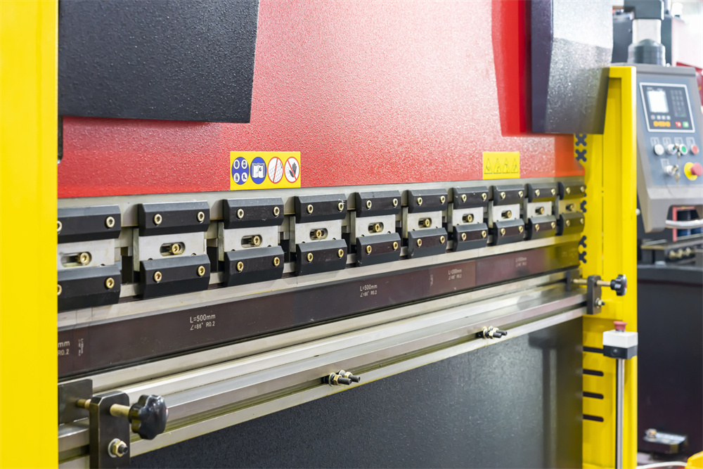
Another vital parameter is the integration of the ‘Crowning System.’ In long press brakes, the bed and ram can deflect under high pressure, leading to uneven angles across the length of the bend. Automated crowning systems use hydraulic or mechanical wedges controlled by the CNC to counteract this deflection in real-time. This ensures that a 4-meter bend is perfectly straight from end to end, a feat that is difficult to achieve consistently with manual adjustments.
Calculation Method: Determining Bending Force and ROI
Calculating the requirements for an automated setup involves both mechanical physics and economic forecasting. To ensure the machine operates within safe limits and provides the desired return on investment, specific formulas and methodologies are applied.
Bending Force Calculation
The required tonnage (P) for a V-bending operation is typically calculated using the following formula:
P = (650 * S^2 * L) / V
Where:
P = Bending force (kN)
S = Material thickness (mm)
L = Bending length (m)
V = V-die opening width (mm)
In an automated environment, the CNC uses this formula (often with additional factors for material tensile strength) to automatically set the pressure limits. This prevents over-tonnage, which can damage tools or the machine frame. Automation improves press brake bending for modern fabrication lines by ensuring these calculations are performed instantly for every bend in a sequence, adjusting parameters on the fly for different material types.
Calculating Automation ROI
When justifying the switch to automation, companies must calculate the Return on Investment (ROI). This involves comparing the Total Cost of Ownership (TCO) of a manual system versus an automated one. The formula for ROI in this context is:
ROI = (Annual Savings – Annual Cost of Automation) / Initial Investment
Annual savings include reduced labor costs (one operator can manage multiple robotic cells), reduced scrap (due to precision and angle sensors), and increased throughput (24/7 operation capability). Often, an automated press brake can replace two to three manual machines, providing a payback period of 18 to 36 months depending on the shift structure and part complexity.
Parameter Table: Manual vs. Automated Press Brake Comparison
The following table highlights the technical differences that demonstrate how automation improves press brake bending for modern fabrication lines.
| Feature | Manual Press Brake | Semi-Automated (CNC) | Fully Automated Robotic Cell |
|---|---|---|---|
| Setup Time | 30 – 60 Minutes | 10 – 20 Minutes | < 5 Minutes (with ATC) |
| Positioning Accuracy | +/- 0.5 mm | +/- 0.1 mm | +/- 0.01 mm |
| Operator Requirement | 1 Skilled Operator per machine | 1 Operator per machine | 1 Technician for 3+ cells |
| Safety Risk | High (Manual handling) | Medium (Light curtains) | Low (Fully enclosed) |
| Consistency | Variable (Operator fatigue) | High | Extreme (24/7 consistency) |
| Complex Part Handling | Difficult / Multi-person | Moderate | Seamless (Robotic rotation) |
| Scrap Rate | 3% – 5% | 1% – 2% | < 0.5% |
Common Engineering Mistakes in Automated Bending
Despite the advantages, implementing automation is not without its pitfalls. Engineering teams often make several common mistakes during the transition to automated press brake bending.
1. Ignoring Material Quality and Consistency
Automation relies on predictability. If the raw sheet metal has significant variations in thickness or internal stress, the robot may struggle to maintain precision. Engineers often fail to specify higher-quality materials or implement pre-processing (like leveling) before the material reaches the automated cell. Without consistent material, the benefits of automation are partially negated by the need for constant manual intervention.
2. Poor Gripper Design
The interface between the robot and the part is the gripper. A common mistake is using a “one-size-fits-all” gripper for a wide variety of parts. If the gripper does not provide adequate support, the part may sag or shift during the bend, leading to inaccuracies. Engineers must carefully design vacuum or magnetic grippers that can adapt to different geometries or implement an automated gripper change station.
3. Overlooking Offline Programming (OLP)
Many shops attempt to program the robot and press brake at the machine (teach-pendant programming). This is highly inefficient and keeps the machine idle. The true power of how automation improves press brake bending for modern fabrication lines lies in Offline Programming. Failing to invest in robust OLP software results in longer downtime and a failure to optimize the bending sequence for speed.
4. Inadequate Safety Integration
While robots remove the operator from the immediate danger zone, they introduce new risks. A common mistake is failing to integrate the robot’s safety circuit with the press brake’s emergency stop system. Modern lines require sophisticated light curtains, area scanners, and interlocked fencing to ensure that the entire cell is safe for maintenance personnel while operating at high speeds.
Selection Checklist for Automated Press Brakes
When selecting a system to improve your fabrication line, use this checklist to ensure all technical and operational requirements are met:
- Software Compatibility: Does the machine software integrate with your existing CAD/CAM systems? Can it handle 3D model imports (STEP, IGES)?
- Tonnage Capacity: Does the machine have a 20% safety margin above your thickest/hardest material requirements?
- Backgauge Versatility: Does the backgauge offer enough axes (at least 4-6) to support the complexity of your parts?
- Robotic Integration: Is the robot’s controller fully integrated with the press brake CNC, or are they running on separate, uncommunicative systems?
- Tooling Library: Does the machine support standard tooling, or are you locked into a proprietary system? Is an Automatic Tool Changer (ATC) available?
- Angle Measurement: Does the system include real-time laser angle tracking for automatic springback compensation?
- Support and Training: Does the manufacturer (like HARSLE) provide comprehensive training for both the machine operation and the robotic programming?
- Future Scalability: Can the system be expanded later with additional material towers, conveyors, or specialized grippers?
Frequently Asked Questions (FAQ)
How does automation improve press brake bending for small batch sizes?
Automation improves small-batch production primarily through Automatic Tool Changers (ATC) and Offline Programming. By reducing setup time from nearly an hour to just a few minutes, it becomes economically viable to run batches as small as five or ten pieces. The software ensures the first part is correct, eliminating the waste associated with traditional setup pieces.
Can an existing manual press brake be retrofitted with automation?
While some basic CNC upgrades are possible, full robotic automation is best implemented on machines designed for it. Modern automated press brakes have specific communication protocols and mechanical interfaces (like hydraulic tool clamping) that are difficult and expensive to retrofit onto older manual machines. For a modern fabrication line, investing in a purpose-built automated cell is usually the more cost-effective long-term solution.
What is ‘Robot Following’ and why is it important?
Robot following is a feature where the robotic arm moves in perfect synchronization with the metal sheet as the press brake ram moves down. This supports the material during the bend, preventing the sheet from bending under its own weight or slipping out of the die. It is crucial for maintaining accuracy and preventing surface scratches on large or heavy parts.
Does automation eliminate the need for skilled operators?
Automation changes the role of the operator rather than eliminating it. Instead of manual lifting and positioning, the operator becomes a ‘Cell Technician.’ They focus on programming, optimizing sequences, and managing the workflow of multiple machines. While it reduces the number of people needed for physical labor, it increases the demand for staff with technical and digital skills.
What are the maintenance requirements for an automated press brake?
Automated systems require regular maintenance of both the hydraulic/mechanical components of the press brake and the electronic/robotic components. This includes lubricating the robotic joints, checking vacuum filters on grippers, calibrating the laser angle sensors, and ensuring the CNC software is updated. A proactive maintenance schedule is essential to prevent downtime in a high-throughput environment.
How does automation handle different material types like aluminum vs. stainless steel?
Automation handles different materials through sophisticated sensors and database-driven software. The CNC controller stores ‘material libraries’ that account for the different springback characteristics of aluminum, mild steel, and stainless steel. When combined with real-time angle measurement, the machine automatically adjusts its stroke depth to achieve the desired angle regardless of the material’s unique properties.