Press Brake Back Gauge Guide: Functions, Settings, and Accuracy Tips


Technical Overview: The Role of the Back Gauge in Modern Bending
In the realm of precision metal fabrication, the press brake back gauge is often referred to as the ‘unsung hero’ of the bending process. While the hydraulic system provides the force and the tooling defines the shape, the back gauge determines the accuracy of the flange length. Without a high-precision back gauge, even the most powerful press brake would struggle to produce consistent parts. At HARSLE, we recognize that the back gauge is the primary interface between the operator’s intent and the physical reality of the workpiece.
A back gauge is a motorized positioning system located at the rear of the press brake. Its primary function is to provide a physical stop for the sheet metal, ensuring that the bend line aligns perfectly with the center of the V-die. Modern CNC (Computer Numerical Control) back gauges have evolved from simple manual stops to complex multi-axis robotic systems. These systems utilize high-precision ball screws, linear guides, and servo motors to achieve positioning accuracies within microns.
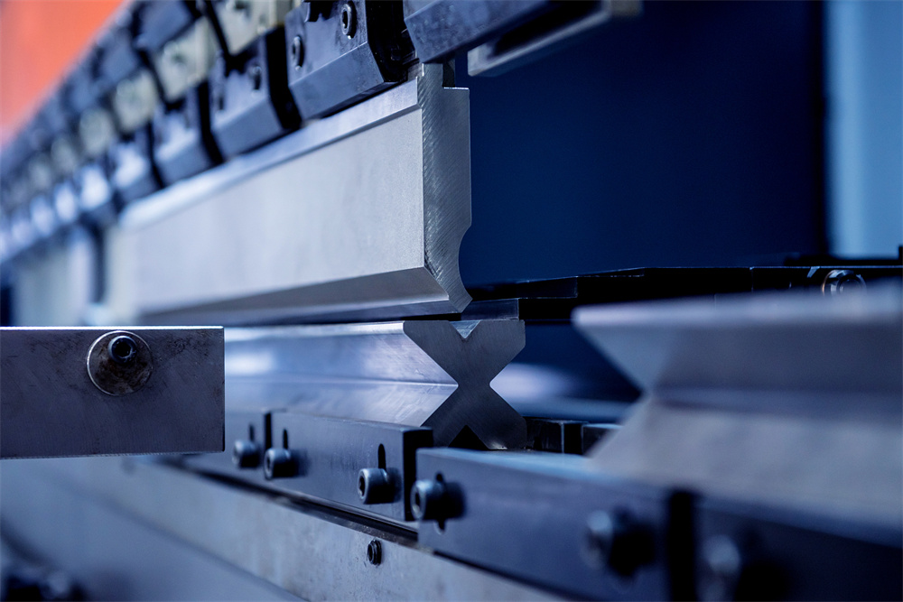
The complexity of a back gauge is usually defined by its ‘axes.’ A standard entry-level machine might feature a 1-axis (X-axis) gauge, which moves forward and backward to set the flange depth. However, high-end HARSLE machines often feature 4-axis, 6-axis, or even 8-axis systems. These additional axes allow for the bending of tapered parts, varying heights (R-axis), and independent movement of the gauge fingers (Z1 and Z2 axes). Understanding these movements is critical for any engineer looking to optimize their production workflow.
Furthermore, the structural integrity of the back gauge is paramount. It must be rigid enough to withstand the impact of heavy steel plates being pushed against it, yet agile enough to move rapidly between different bend steps. The use of aircraft-grade aluminum for the gauge bar and hardened steel for the fingers is a common practice to balance weight and durability. In the following sections, we will delve deeper into the specific parameters and settings that define a world-class back gauge system.
Core Parameters: Understanding Axis Movements and Specifications
To master the Press Brake Back Gauge : Functions, Settings, Accuracy Tips, one must first understand the nomenclature of the axes. Each axis serves a specific geometric purpose. The X-axis is the most fundamental, controlling the depth of the bend. When you program a flange length of 50mm, the X-axis moves the gauge fingers to a position that accounts for the material thickness and the bend deduction to ensure the final external dimension is exactly 50mm.
The R-axis controls the vertical height of the back gauge. This is essential when using dies of different heights or when a part has a pre-bent flange that would otherwise collide with the gauge bar. An automated R-axis allows the CNC controller to lift or lower the gauge fingers dynamically between steps, significantly reducing setup time and preventing mechanical interference. Without an R-axis, operators are often forced to manually shim the gauge, which introduces human error and slows down production.
Z-axis movements (Z1 and Z2) refer to the lateral movement of the gauge fingers along the length of the machine. In a standard setup, the fingers move together. However, in a multi-axis system, Z1 and Z2 can move independently. This is particularly useful for bending small parts side-by-side or for supporting long, narrow strips that require specific support points to prevent sagging. Some advanced systems also include X1 and X2 axes, allowing the fingers to move independently in the depth direction, which is the secret to creating perfectly tapered bends.
Beyond the axes themselves, technical specifications such as ‘Repeatability’ and ‘Positioning Speed’ are vital. Repeatability refers to the machine’s ability to return to the exact same spot time after time. For high-precision electronics or aerospace components, a repeatability of ±0.01mm is often required. Positioning speed, measured in millimeters per second (mm/s), dictates the cycle time of the machine. Faster back gauges allow for higher throughput, especially in complex parts with 10 or more bends.
Calculation Method: Aligning the Gauge with Bend Geometry
Calculating the correct back gauge position is not as simple as entering the desired flange length. The CNC controller must account for the ‘Bend Deduction’ (BD) or ‘Bend Allowance’ (BA). When sheet metal is bent, the outer surface stretches and the inner surface compresses. The ‘Neutral Axis’ is the theoretical plane where no deformation occurs. The back gauge must be positioned relative to the ‘theoretical sharp’ or the center of the die, depending on the programming mode used.
The standard formula for back gauge positioning (X-axis) for a 90-degree bend is:
X = L – (V/2) – K
Where ‘L’ is the desired flange length, ‘V’ is the die width, and ‘K’ is a constant factor that accounts for material deformation. However, most modern HARSLE CNC controllers, such as the Delem or Cybelec systems, perform these calculations automatically once the material type, thickness, and die parameters are entered. The operator simply inputs the dimensions from the blueprint, and the software handles the trigonometry.
Accuracy tips for calculation involve the ‘K-factor.’ The K-factor varies depending on the material’s ductility. For example, stainless steel behaves differently than aluminum. If your back gauge is consistently off by a fraction of a millimeter, it is often not a mechanical calibration issue but rather an incorrect K-factor in the controller settings. Testing a scrap piece of the same material batch is the most reliable way to ‘dial in’ the calculation before starting a production run.
Another critical calculation involves the ‘Gauge Finger Offset.’ The fingers themselves have a physical thickness and a specific contact point (often a 5mm or 10mm step). If the operator uses the wrong step on the finger without updating the controller, the entire batch will be scrapped. Always verify that the ‘Finger Type’ selected in the CNC software matches the physical hardware installed on the back gauge bar.
Parameter Table: Axis Comparison and Capabilities
The following table outlines the typical capabilities of various back gauge configurations found in industrial press brakes. This serves as a reference for selecting the right machine for your specific fabrication needs.
| Axis Configuration | Movement Description | Primary Application | Accuracy/Repeatability |
|---|---|---|---|
| X-Axis Only | Forward/Backward | Simple 90-degree bends, single flange depths. | ±0.05 mm |
| X + R | Depth + Height | Parts with multiple flange heights or varying die sets. | ±0.03 mm |
| X + R + Z1 + Z2 | Depth, Height, Lateral | Complex parts, asymmetrical shapes, high-volume production. | ±0.02 mm |
| X1 + X2 + R1 + R2 + Z1 + Z2 | Independent 6-Axis | Tapered bends, aerospace components, extreme precision. | ±0.01 mm |
| CNC Crowning (Related) | Bed Compensation | Ensuring constant angle across long workpieces. | N/A (Angular) |
Common Engineering Mistakes in Back Gauge Operation
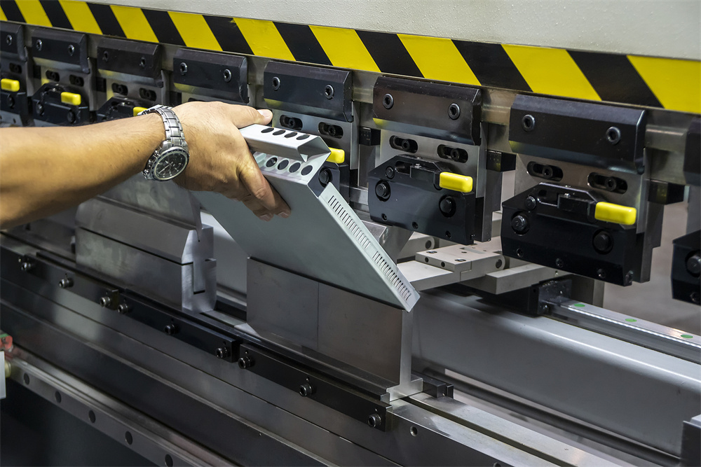
One of the most frequent mistakes in metal fabrication is neglecting the ‘Parallelism’ of the back gauge. Over time, due to collisions or heavy use, the back gauge bar may become slightly skewed relative to the ram. Even a 0.5mm deviation across a 3-meter bed can result in parts that are out of square. Regular calibration using a dial indicator is essential to ensure that the X-axis is perfectly perpendicular to the bending plane.
Another common error is ‘Over-Pushing.’ Operators sometimes push the sheet metal too forcefully against the gauge fingers, causing the back gauge to deflect or the sheet to slightly deform before the pinch point is reached. This is especially problematic with thin-gauge materials. To combat this, HARSLE machines feature ‘Retract’ settings, where the back gauge moves back slightly just before the punch touches the metal, ensuring the part isn’t trapped or pushed out of alignment during the bend.
Ignoring the ‘Minimum Flange Length’ is a technical oversight that can lead to back gauge damage. Every die has a minimum flange requirement to ensure the metal spans the V-opening. If an engineer attempts to bend a flange that is too short, the material may slip into the die, and the back gauge fingers may be struck by the descending punch. Always cross-reference your back gauge position with the die’s safe operating limits.
Finally, poor maintenance of the drive system is a silent killer of accuracy. Dust, metal shavings, and dried grease can accumulate on the ball screws and linear rails. This increases friction, leading to ‘lost motion’ or backlash. A back gauge that ‘stutters’ or makes a grinding noise is a sign that the servo motors are struggling against debris. A weekly cleaning and lubrication schedule is the simplest way to maintain the Press Brake Back Gauge : Functions, Settings, Accuracy Tips standards required for high-end work.
Selection Checklist: Choosing the Right Back Gauge for Your Shop
When investing in a new HARSLE press brake or upgrading an existing one, use this checklist to ensure the back gauge meets your long-term requirements:
- Number of Axes: Do you perform tapered bends? If yes, independent X1/X2 axes are mandatory. If you only do box bending, a 4-axis (XRZ1Z2) system is usually the ‘sweet spot’ for ROI.
- Drive Mechanism: Ensure the system uses high-quality ball screws rather than belt drives for the X-axis. Ball screws offer superior longevity and precision under heavy loads.
- Finger Design: Look for multi-step fingers. These allow you to gauge different flange lengths without moving the X-axis as much, and they provide better support for large sheets.
- Controller Integration: Is the back gauge fully integrated with the CNC? You should be able to see a 3D visualization of the back gauge movement to check for collisions before the first bend.
- Safety Features: Does the system have ‘collision protection’? Some modern gauges are designed to ‘break away’ or trigger an emergency stop if they hit an obstruction, preventing thousands of dollars in repair costs.
- Speed and Acceleration: For high-volume shops, the ‘station-to-station’ time is critical. Check the mm/s rating for the X and R axes.
FAQ: Troubleshooting and Accuracy Optimization
How often should I calibrate my press brake back gauge?
For standard production, a monthly calibration check is recommended. However, if the machine experiences a ‘crash’ (where the punch or material hits the gauge bar), immediate recalibration is necessary. High-precision shops often perform a quick zero-point check at the start of every shift.
Why is my flange length inconsistent even though the back gauge is moving correctly?
Inconsistency is often caused by material variations (thickness or hardness) or ‘springback.’ If the back gauge is mechanically sound, check if the material is sliding during the bend. Using a ‘pinch point’ or slowing down the approach speed of the ram can help stabilize the part against the gauge.
Can I add more axes to my back gauge later?
While some modular systems allow for upgrades, it is generally much more cost-effective to purchase the required axes at the time of machine manufacture. Adding an R-axis or independent Z-axes later requires significant hardware and software reconfiguration.
What is the ‘Retract’ function, and when should I use it?
The retract function tells the back gauge to move away from the part once the punch has ‘pinched’ the metal. This is used to prevent the part from scraping against the fingers as it rotates upward during the bend, which protects both the part finish and the back gauge mechanics.
How do I handle very large sheets that sag?
For large sheets, the back gauge fingers alone may not provide enough support. In these cases, ‘Sheet Supports’ or ‘Front Followers’ should be used in conjunction with the back gauge to ensure the material remains flat and accurately positioned against the stops.