Punching Machine Die Design Basics for Precision Metal Hole Making


Technical Overview of Punching Machine Die Design
In the realm of industrial metal fabrication, the efficiency and accuracy of hole-making processes are fundamentally dictated by the quality and design of the punching dies. Punching machine die design basics for precision metal hole making involve a complex interplay of mechanical engineering, material science, and fluid dynamics. At its core, the punching process is a shearing operation where a punch and a die work in tandem to create a specific geometry in a metal sheet. HARSLE, a leader in metal fabrication machinery, emphasizes that understanding the physics of the fracture zone is essential for any engineer looking to optimize production cycles.
The process begins when the punch descends onto the workpiece, which is supported by the die. Initially, the metal undergoes elastic deformation, followed by plastic deformation as the punch penetrates deeper. Eventually, the internal stresses exceed the material’s ultimate tensile strength, leading to a controlled fracture. The quality of this fracture—characterized by the burnish zone, the break-out, and the burr height—is entirely dependent on the die design. Precision metal hole making requires a design that minimizes tool wear while maximizing the clean-cut surface of the hole.
Modern CNC punching machines, such as those manufactured by HARSLE, utilize sophisticated die sets that can handle high-speed operations. However, even the most advanced machine cannot compensate for a poorly designed die. The design must account for the specific properties of the material being processed, including its thickness, tensile strength, and ductility. A well-designed die ensures that the energy transferred from the machine is used efficiently to shear the metal rather than generating excessive heat or causing structural deformation in the workpiece.
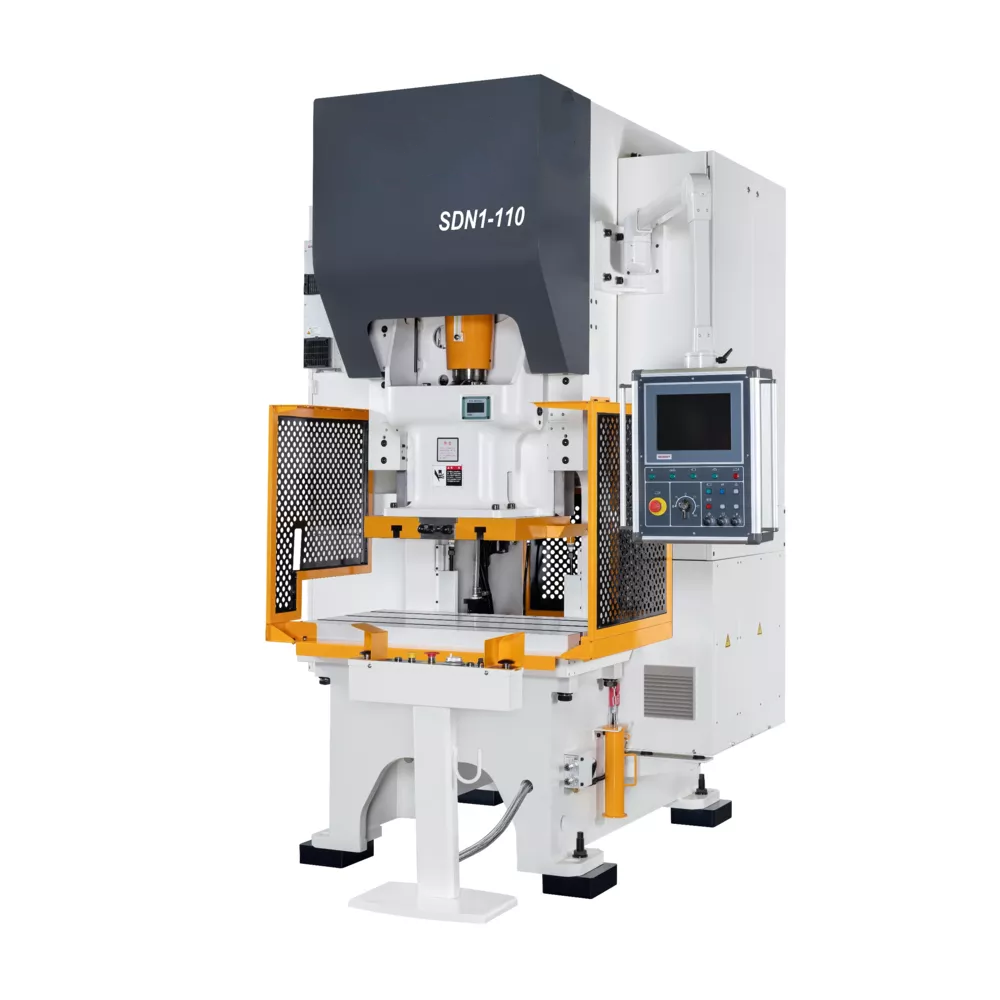
Furthermore, the technical overview must include the role of the stripper plate and the die holder. The stripper plate is not merely a safety feature; it holds the material flat during the punch and ensures the punch retracts cleanly without pulling the material upward. This is vital for maintaining the flatness of the sheet, especially in thin-gauge precision components. The die holder, or bolster, must provide rigid support to prevent any deflection that could lead to misalignment between the punch and the die opening.
Core Parameters in Die Design
When discussing punching machine die design basics for precision metal hole making, several core parameters stand out as the pillars of a successful operation. The most critical of these is Die Clearance. Clearance is the space between the punch and the die opening. If the clearance is too small, the fracture lines from the top and bottom do not meet, causing secondary shearing and excessive tool wear. Conversely, if the clearance is too large, the material is drawn into the die, resulting in large burrs and a tapered hole profile.
Another essential parameter is the Shear Angle. While many small punches are flat-faced, larger punches often incorporate a shear angle (also known as a roof-top or valley shear). This angle reduces the peak punching force required by ensuring that the entire circumference of the hole is not cut simultaneously. By spreading the load over a longer stroke, the machine experiences less shock, which extends the life of both the die and the punching machine itself.
Punch and Die Radii also play a significant role. Sharp edges are necessary for clean cuts, but microscopic radii are often engineered into the tools to prevent chipping under high-stress conditions. The choice of tool steel—such as D2, M2, or powdered metals—is a parameter that affects the longevity and thermal stability of the die. For precision metal hole making, the tool material must resist both abrasive wear (from the metal sliding against the tool) and adhesive wear (where the workpiece material sticks to the tool).
Lastly, the Stripping Force must be calculated accurately. This is the force required to pull the punch out of the material after the hole is made. Factors such as material thickness, lubrication, and the surface finish of the punch influence this force. Inadequate stripping force can lead to “slug pulling,” where the waste material sticks to the punch and is lifted back onto the sheet, causing damage in the subsequent stroke.
Calculation Method for Precision Punching
To achieve precision metal hole making, engineers must rely on precise mathematical formulas rather than guesswork. The primary calculation is the Punching Force (P). The standard formula is P = L × t × τ, where ‘L’ is the perimeter of the hole, ‘t’ is the material thickness, and ‘τ’ is the shear strength of the material. It is standard practice to add a 20-30% safety margin to this calculation to account for tool dulling and variations in material hardness.
Calculating the Optimal Die Clearance is equally vital. Clearance is typically expressed as a percentage of the material thickness per side. For mild steel, a common clearance is 5% to 8% of the thickness. For harder materials like stainless steel, this might increase to 10% or 12%. The formula for total clearance (C) is C = c × t, where ‘c’ is the clearance constant for the specific material. Precision applications often require tighter tolerances, necessitating a more granular approach to these constants.
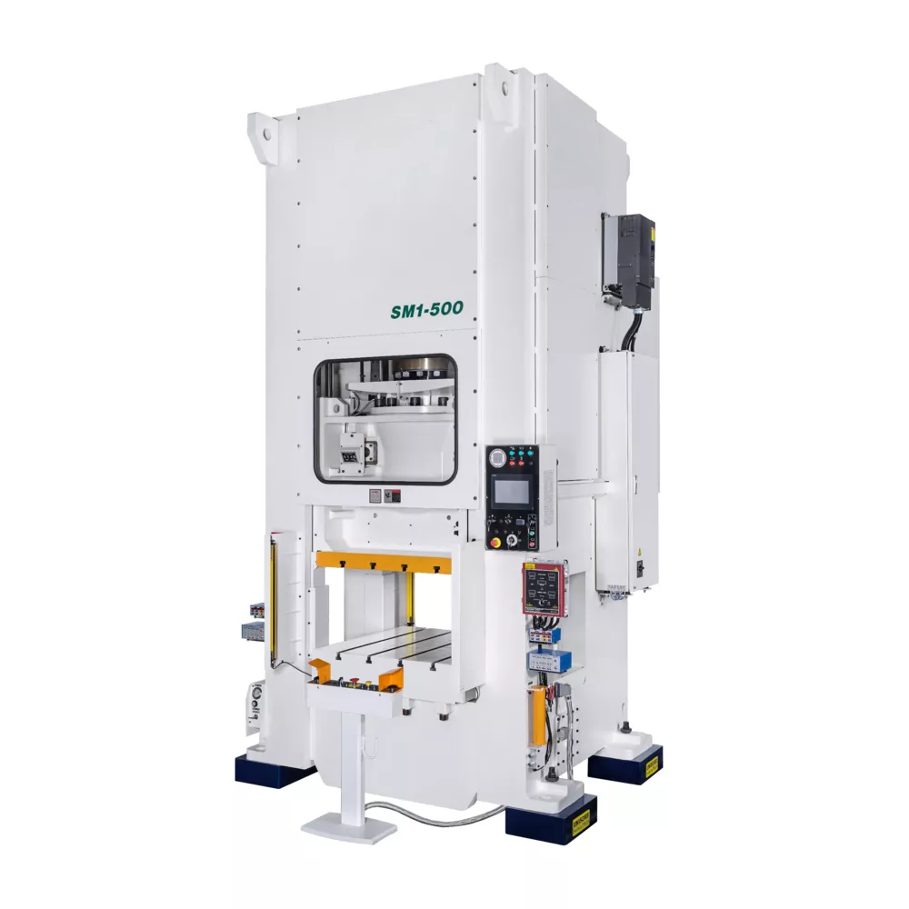
The Press Capacity must also be verified. The total force required (including stripping force) should not exceed 80% of the machine’s rated capacity for continuous operation. Overloading the machine leads to frame deflection, which ruins the alignment of the precision dies. Furthermore, calculating the Slug Ejection Force is necessary to ensure that the waste material falls freely through the die bed. If the slug is not ejected, it can stack up and cause a catastrophic die failure.
Finally, the Heat Generation during high-speed punching must be considered. As the punch penetrates the metal, friction generates significant heat. The calculation of the thermal expansion of the punch is necessary for high-volume runs to ensure that the punch does not expand to the point of seizing within the die. This is particularly important in precision metal hole making where tolerances are measured in microns.
Parameter Table: Recommended Die Clearances
The following table provides a general guideline for die clearances based on material type and thickness. These values are essential for punching machine die design basics for precision metal hole making.
| Material Type | Thickness Range (mm) | Recommended Clearance (% of Thickness) | Expected Hole Quality |
|---|---|---|---|
| Mild Steel (CR) | 0.5 – 3.0 | 5% – 8% | High – Minimal Burr |
| Stainless Steel (304/316) | 0.5 – 2.5 | 10% – 12% | Medium – Work Hardening Possible |
| Aluminum (Soft) | 1.0 – 5.0 | 3% – 5% | High – Smooth Edge |
| High-Strength Steel | 2.0 – 6.0 | 15% – 20% | Low – Significant Breakout |
| Copper/Brass | 0.5 – 4.0 | 4% – 6% | Excellent – Precision Finish |
Common Engineering Mistakes in Die Design
One of the most frequent mistakes in punching machine die design is ignoring the material grain direction. Metal sheets have a grain resulting from the rolling process. Punching across the grain versus along the grain can result in different fracture patterns and burr heights. In precision metal hole making, failing to orient the part correctly can lead to inconsistent dimensions across a production batch.
Another common error is insufficient lubrication. Many designers assume the machine’s automatic oiler is enough, but specific high-friction operations require specialized lubricants applied directly to the punch or the sheet. Without proper lubrication, “galling” occurs—where the workpiece material cold-welds itself to the punch. This increases the stripping force and eventually leads to tool breakage or damaged workpieces.
Improper Slug Management is a third major pitfall. If the die land (the straight portion of the die opening) is too long, slugs can become trapped. If it is too short, the slugs may bounce back up. Designers must incorporate “slug-hugger” features or vacuum systems in high-precision environments to ensure that every waste piece is successfully removed from the work area. A single trapped slug can destroy a multi-thousand-dollar die set in one stroke.
Finally, many engineers overlook the impact of heat treatment on the die components. A die that is too hard will be brittle and prone to cracking under the shock of punching, while a die that is too soft will wear down rapidly, losing its precision. Achieving the correct Rockwell hardness (HRC) for the specific application is a cornerstone of punching machine die design basics for precision metal hole making.
Selection Checklist for Punching Dies
When selecting or designing a die for your HARSLE punching machine, use the following checklist to ensure all precision requirements are met:
- Material Compatibility: Is the die material (e.g., D2, M2) appropriate for the workpiece material and thickness?
- Clearance Verification: Has the clearance been calculated based on the specific tensile strength of the current batch of metal?
- Coating Requirements: Does the punch require a TiN or TiCN coating to reduce friction and extend tool life?
- Alignment Precision: Are the guide bushings and pins within the required tolerance to ensure perfect punch-to-die centering?
- Slug Control: Does the die design include features to prevent slug pulling or stacking?
- Maintenance Access: Can the punch and die be easily removed for sharpening without dismantling the entire machine setup?
- Tonnage Check: Is the calculated punching force well within the machine’s safe operating limits?
- Stripper Plate Pressure: Is the stripper spring pressure sufficient to prevent material deformation during the return stroke?
Frequently Asked Questions (FAQ)
1. How often should punching dies be sharpened?
Sharpening frequency depends on the material being punched and the tool quality. A general rule is to sharpen the punch and die when the burr height exceeds 10% of the material thickness. Regular maintenance, such as removing 0.01mm to 0.05mm of material, is better than waiting for significant dulling.
2. What causes a punch to break suddenly?
Sudden breakage is usually caused by misalignment, excessive hardness of the tool (brittleness), or punching a material that is thicker than the tool’s design limit. It can also occur if a slug from a previous stroke remains in the die.
3. Can I use the same die for different materials?
While possible, it is not recommended for precision metal hole making. Different materials require different clearances. Using a die designed for aluminum on stainless steel will result in poor hole quality and rapid tool wear.
4. What is the benefit of a coated punch?
Coatings like Titanium Nitride (TiN) increase surface hardness and reduce friction. This allows for higher punching speeds, reduces heat buildup, and significantly extends the time between sharpenings.
5. How does die clearance affect the hole size?
In punching, the hole size is determined by the punch diameter, while the slug size is determined by the die diameter. If you need a precise hole size, you must size the punch accordingly and adjust the die diameter to provide the correct clearance.
6. Why is my punching machine vibrating excessively?
Excessive vibration often indicates that the punching force is too high for the machine’s frame or that the punches lack a shear angle. Adding a roof-top shear to the punch can significantly reduce the shock and vibration during the operation.