Comprehensive Guide: Common Press Brake Back Gauge Problems and How to Troubleshoot Them


Introduction to Press Brake Back Gauge Systems
In the world of precision metal fabrication, the back gauge is often considered the unsung hero of the press brake. While the hydraulic system provides the force and the tooling defines the shape, the back gauge ensures that every bend is placed exactly where it needs to be. For operators and shop managers, understanding Common Press Brake Back Gauge Problems Troubleshoot Them is essential for maintaining high productivity and minimizing scrap rates. A back gauge that is out of alignment or malfunctioning can lead to thousands of dollars in wasted material and lost labor time.
Modern CNC back gauges are complex mechatronic systems involving high-precision ball screws, linear guides, servo motors, and sophisticated software interfaces. They are designed to move rapidly between bends, often positioning within microns of the target. However, the harsh environment of a fabrication shop—filled with metal dust, vibrations, and heavy workloads—can take a toll on these components. Whether you are using a simple two-axis gauge or a complex six-axis system (X, R, Z1, Z2, X1, X2), the principles of troubleshooting remain largely the same.
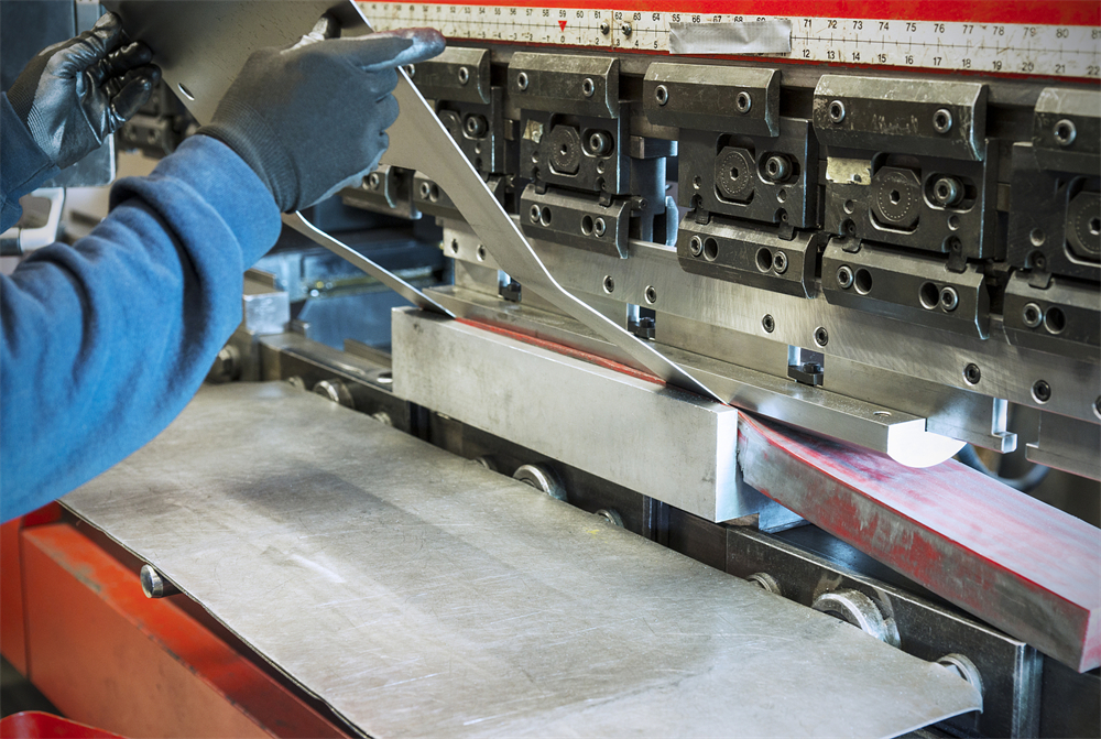
HARSLE has spent decades refining back gauge technology to provide maximum durability. Yet, even the best equipment requires regular attention. This article serves as a comprehensive technical resource for identifying, diagnosing, and resolving the most frequent issues encountered with back gauge systems. By following these professional troubleshooting steps, you can ensure your press brake remains a reliable asset in your production line.
Key Considerations for Back Gauge Performance
Before diving into specific troubleshooting steps, it is vital to understand the factors that influence back gauge performance. The primary metrics for any back gauge are accuracy, repeatability, and speed. Accuracy refers to the gauge’s ability to move to the exact coordinate requested by the CNC controller. Repeatability is the gauge’s ability to return to that same position consistently over hundreds of cycles. If either of these is compromised, the quality of the finished part will suffer.
Another key consideration is the axis configuration. A standard X-axis controls the depth of the bend, while the R-axis controls the height of the gauge fingers. Z-axes (Z1 and Z2) allow the fingers to move left and right to accommodate different part widths. In more advanced setups, independent X1 and X2 axes allow for tapered bending. Each additional axis introduces more mechanical components and electrical connections, increasing the potential points of failure. When troubleshooting, it is important to isolate which specific axis is exhibiting the problem to narrow down the cause.
Environmental factors also play a significant role. Temperature fluctuations in a non-climate-controlled shop can cause thermal expansion of the metal components, leading to slight deviations in accuracy. Furthermore, the accumulation of fine metal dust on the linear guides can increase friction, leading to premature wear or motor stalls. Understanding these external influences is the first step in a proactive maintenance and troubleshooting strategy.
Technical Details: The Anatomy of a Back Gauge
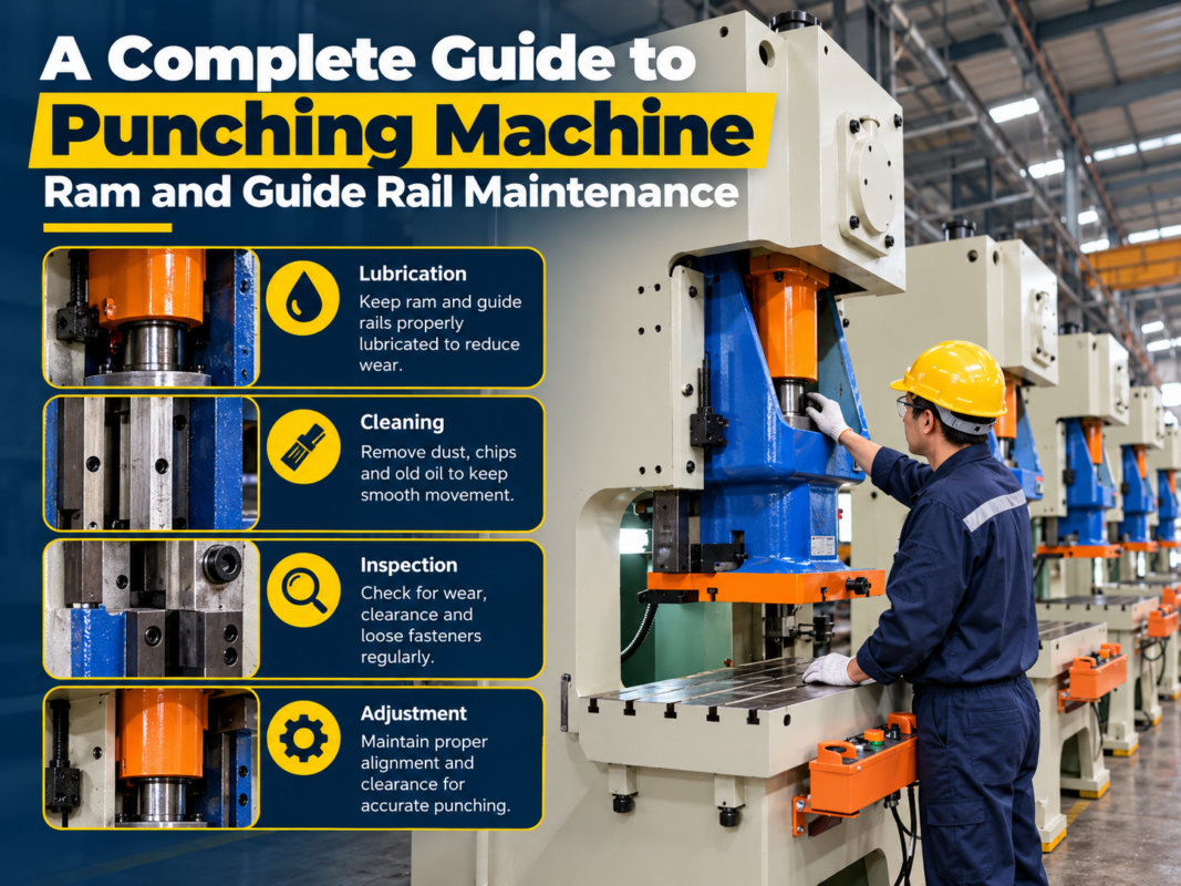
To effectively address Common Press Brake Back Gauge Problems Troubleshoot Them, one must understand the mechanical and electrical components that make up the system. At the heart of most CNC back gauges is the ball screw assembly. The ball screw converts the rotary motion of the servo motor into precise linear motion. Because ball screws use recirculating ball bearings, they offer high efficiency and minimal backlash compared to traditional lead screws. However, if the lubrication fails or if debris enters the nut, the balls can flat-spot or the track can become pitted, leading to “jumpy” movement or loss of precision.
The linear guides or rails provide the path for the back gauge carriage. These must be perfectly parallel to ensure smooth travel. Any misalignment in the rails can cause the carriage to bind, putting excessive load on the servo motor. This often manifests as a “Motor Overload” error on the CNC controller. The carriage itself holds the gauge fingers, which are the physical contact points for the workpiece. These fingers must be checked for wear and squareness regularly, as they are the final link in the accuracy chain.
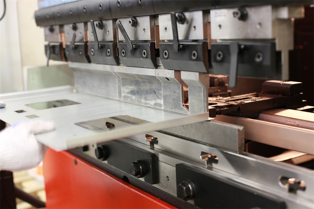
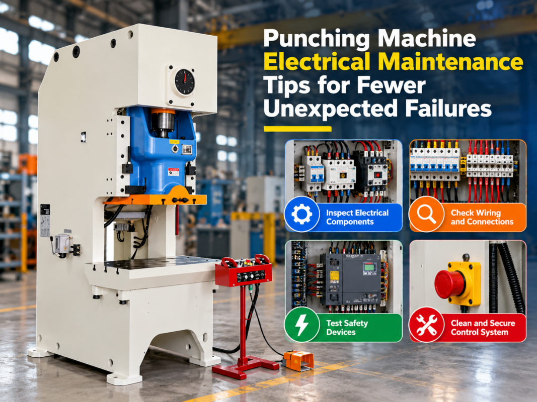
On the electrical side, the system consists of the CNC controller, servo drives, servo motors, and encoders. The encoder is a critical component that provides feedback to the controller regarding the motor’s actual position. If there is a discrepancy between the commanded position and the feedback from the encoder, the system will trigger an error. Wiring harnesses that flex during movement are also common failure points; over time, the internal copper strands can break, leading to intermittent signals that are notoriously difficult to diagnose without a systematic approach.
Common Press Brake Back Gauge Problems and How to Troubleshoot Them
1. Inconsistent Bend Dimensions (Accuracy Issues)
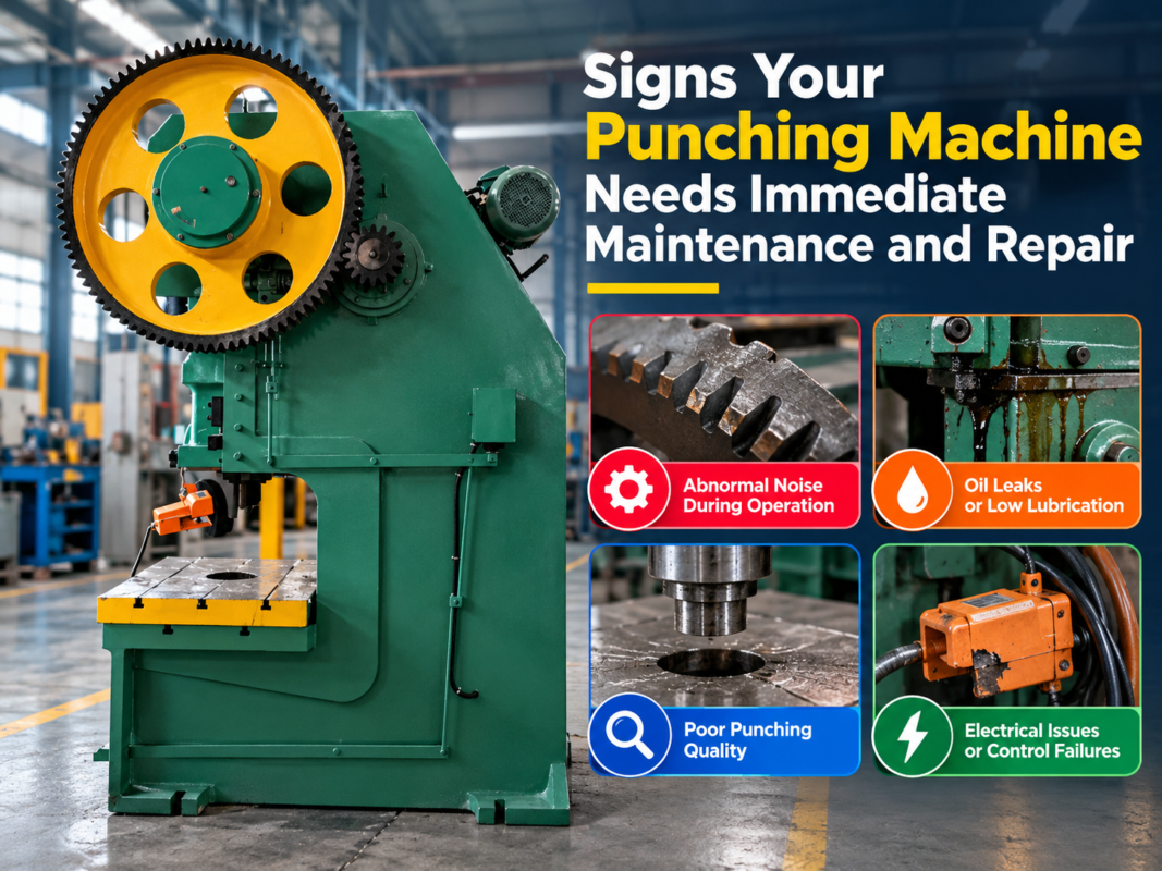
One of the most frequent complaints is that the bend length varies from part to part or deviates from the programmed value. This is often caused by mechanical backlash. Backlash occurs when there is play between the ball screw and the nut, or in the couplings between the motor and the screw. To troubleshoot, power down the machine and attempt to physically move the back gauge carriage by hand. If there is noticeable movement, check the tightness of the motor couplings and the wear on the ball screw nut.
Another cause for accuracy issues is improper calibration. Most CNC controllers have a calibration routine where the gauge moves to a hard stop or a reference sensor. If the reference sensor is dirty or loose, the “zero point” of the machine will be off. Clean the sensors and re-run the calibration sequence. Additionally, check the gauge fingers for wear; if the face of the finger is worn down by even 0.1mm, every part produced will be off by that amount.
2. Excessive Noise or Vibration During Movement
If the back gauge makes a grinding or squealing noise while moving, the most likely culprit is a lack of lubrication. The linear guides and ball screws require specific grease to operate smoothly. If the grease has dried out or been contaminated with metal dust, friction increases significantly. Clean the rails thoroughly with a lint-free cloth and apply the manufacturer-recommended lubricant. Do not use WD-40 or similar penetrating oils, as they can wash away the existing grease and provide no long-term lubrication.
Vibration can also stem from loose mounting bolts. The back gauge is subject to constant acceleration and deceleration, which can vibrate bolts loose over time. Periodically check the torque on all mounting hardware, including the bolts securing the back gauge assembly to the main frame of the press brake. If the vibration persists after lubrication and tightening, the bearings within the servo motor or the ball screw nut may be failing and require replacement.
3. Back Gauge Fails to Move or Hits Software Limits
When a back gauge refuses to move, the first step is to check the CNC controller for error codes. Common codes include “Servo Alarm,” “Overload,” or “Communication Error.” If a servo alarm is present, check the drive in the electrical cabinet for specific fault lights. Often, a simple reset of the main power can clear a temporary glitch. However, if the problem persists, check the cables for any signs of pinching or fraying, especially in the cable carrier (drag chain).
If the gauge moves but stops prematurely, it may be hitting a software limit. This happens if the controller thinks the gauge is further along the axis than it actually is. This is usually a calibration issue. Re-home the machine to reset the coordinate system. Also, ensure that no physical obstructions (like dropped parts or tools) are blocking the path of the gauge, as modern systems will stop immediately upon sensing an unexpected resistance to prevent damage.
4. Fingers Are Not Square to the Die
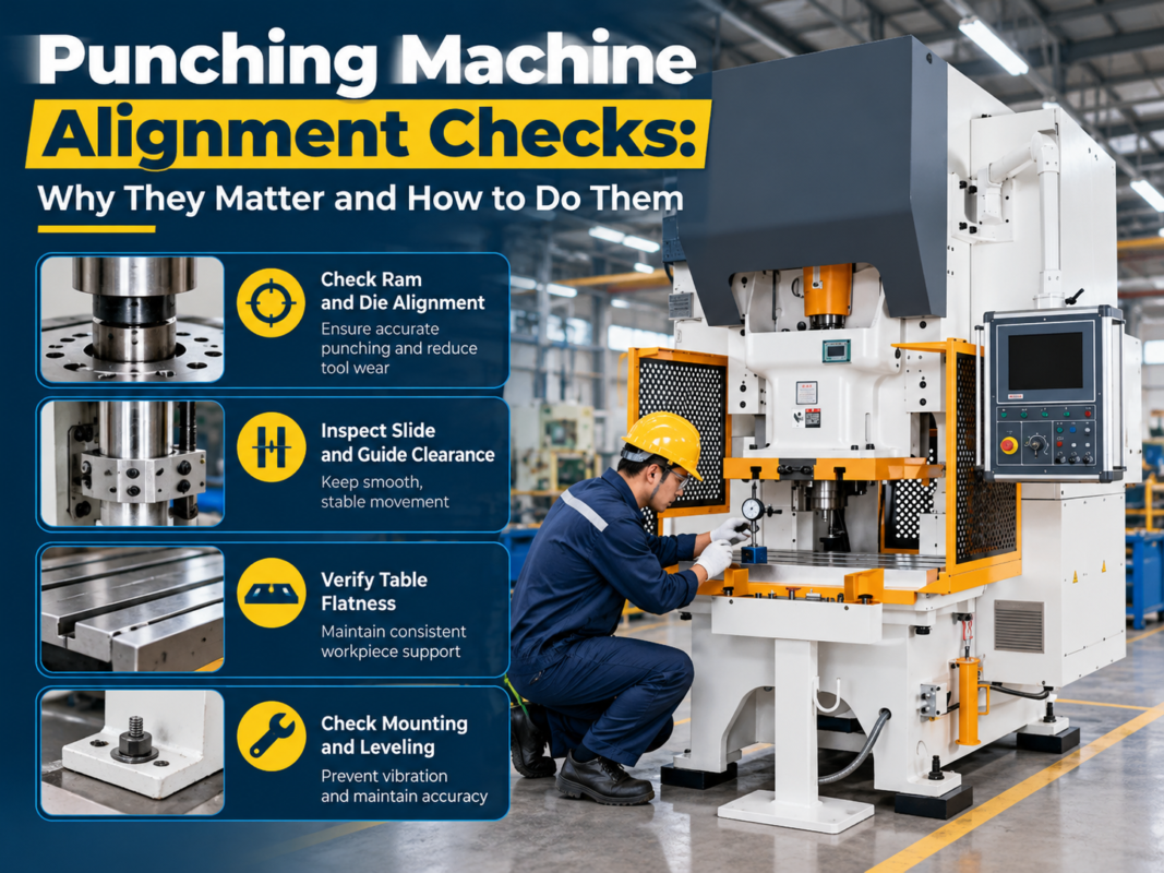
For a bend to be accurate across the entire length of the part, the back gauge fingers must be perfectly parallel to the center of the V-die. If one side of your part is longer than the other, the gauge bar may be skewed. To troubleshoot, use a precision ground block or a dial indicator to measure the distance from the die to the gauge fingers at both ends of the bar. Most back gauges have adjustment bolts that allow you to “tram” the bar back into alignment. This should be done whenever the machine is moved or after a significant collision.
Selection Advice for High-Performance Back Gauges
When purchasing a new press brake or upgrading an existing one, the choice of back gauge is critical. For high-volume production of complex parts, a 4-axis (X, R, Z1, Z2) or 6-axis system is highly recommended. These systems allow for much faster setups because the fingers position themselves automatically for different bend lengths and widths. This eliminates the need for the operator to manually slide fingers along the bar, reducing downtime and the risk of human error.
Look for back gauges that utilize high-quality components, such as HIWIN linear guides or Yaskawa servo motors. The rigidity of the back gauge frame is also paramount. A flimsy back gauge will flex when a heavy plate is pushed against it, leading to inconsistent bends. HARSLE machines are engineered with heavy-duty back gauge assemblies that maintain their precision even under the pressure of large-format sheet metal. Additionally, consider the “reach” of the back gauge; ensure the X-axis travel is sufficient for the largest parts you intend to produce.
Finally, evaluate the CNC controller’s back gauge management software. The interface should be intuitive, allowing for easy calibration and manual offsets. Features like “back gauge retract” are essential; this function moves the gauge away from the part just before the bend is completed, preventing the part from “kicking” against the fingers as it forms upward, which can damage the gauge and ruin the part.
Preventive Maintenance Checklist
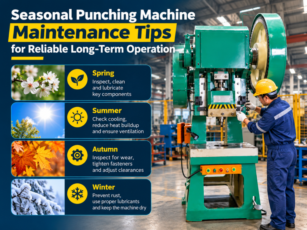
To avoid the need for extensive Common Press Brake Back Gauge Problems Troubleshoot Them, implement a strict preventive maintenance schedule. A well-maintained machine rarely fails unexpectedly.
- Daily: Wipe down the linear rails and ball screws to remove dust. Check for any obvious signs of loose components or oil leaks.
- Weekly: Check the tension of any drive belts. Ensure the gauge fingers are clean and free of burrs that could scratch the workpiece.
- Monthly: Apply fresh grease to all lubrication points. Check the cooling fans in the electrical cabinet to ensure the servo drives aren’t overheating.
- Quarterly: Perform a full calibration and squareness check using precision instruments. Inspect the cable carriers for wear or broken links.
- Annually: Have a certified technician perform a comprehensive system check, including checking the backlash in the ball screws and the integrity of the electrical grounding.
Frequently Asked Questions (FAQ)
How do I know if my back gauge needs calibration?
If you program a 50mm flange and consistently get 50.5mm or 49.5mm across the entire length of the part, your gauge likely needs a calibration offset. If the error is inconsistent, the problem is more likely mechanical wear or backlash.
Can I repair a damaged ball screw?
In some cases, a ball screw can be re-balled by a specialist. However, if the screw shaft itself is scored or bent, replacement is usually the only reliable option to restore original precision.
Why does my back gauge move slowly in cold weather?
Cold temperatures increase the viscosity of the grease on the rails and ball screws, creating more drag. It is recommended to run the back gauge through its full range of motion several times at the start of a shift to “warm up” the lubricant.
What is the ‘R-axis’ and why is it important?
The R-axis controls the vertical height of the back gauge. This is crucial when using different heights of dies. Without an R-axis, you would have to manually shim or adjust the fingers every time you changed the lower tool.
Is it possible to add more axes to my existing back gauge?
This depends on the CNC controller and the mechanical design of the machine. While some systems are modular, it is often more cost-effective to specify the required axes at the time of the original machine purchase.
Conclusion
Mastering the nuances of Common Press Brake Back Gauge Problems Troubleshoot Them is a vital skill for any modern fabricator. By understanding the interplay between mechanical precision and electronic control, you can keep your press brake running at peak efficiency. Regular cleaning, consistent lubrication, and a proactive approach to calibration will prevent the majority of common issues. When problems do arise, a systematic troubleshooting process—starting with the simplest mechanical checks before moving to complex electrical diagnostics—will save time and reduce frustration.
At HARSLE, we are committed to providing not only world-class machinery but also the knowledge required to maintain it. Our back gauge systems are built for the rigors of industrial use, featuring robust components and user-friendly interfaces. By following the guidelines in this article, you can ensure that your HARSLE press brake continues to deliver the precision and reliability your business depends on for years to come.