Press Brake Tooling Guide: Punches, Dies, and Setup Tips for Better Results


Technical Overview: The Science of Press Brake Tooling
In the world of precision metal fabrication, the press brake is only as capable as the tooling it employs. Press Brake Tooling : Punches, Dies, Setup Tips Better Results are the fundamental pillars that determine the accuracy, repeatability, and quality of a finished bend. While the machine provides the force and the CNC system provides the control, the punch and die are the components that physically interface with the material. Understanding the technical nuances of these tools is essential for any operator or engineer looking to optimize production efficiency.
Press brake tooling is generally categorized by the bending method used: air bending, bottoming, or coining. Air bending is the most common modern technique, where the punch presses the material into the die cavity without touching the bottom of the V. This allows for a wide range of angles to be produced with a single set of tools. Bottoming requires the punch to press the material against the die surface, providing higher accuracy but requiring specific tools for each angle. Coining, the most high-pressure method, actually deforms the material at the bend point to eliminate springback entirely. Each method requires specific punch and die geometries to succeed.
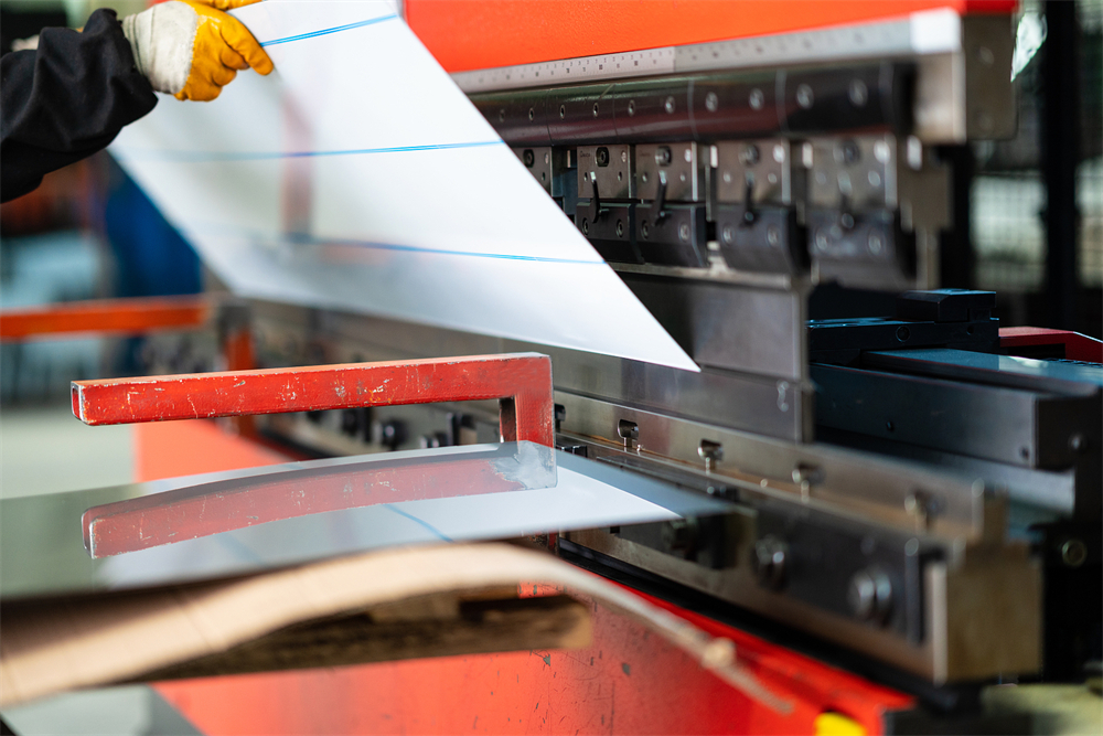
Modern tooling is typically manufactured from high-grade alloy steels like 42CrMo or T8/T10 tool steel. These materials undergo rigorous heat treatment processes, including induction hardening on the working surfaces, to reach a hardness of 45-50 HRC. This ensures that the tools can withstand thousands of tons of pressure without deforming or losing their profile. HARSLE emphasizes the importance of using precision-ground tooling, which ensures that the centerlines of the punch and die remain perfectly aligned across the entire length of the machine bed.
Furthermore, the evolution of clamping systems—such as the New Standard, European (Amada/Promecam), and American styles—has revolutionized setup times. Quick-change clamping allows operators to swap out segments of tooling in seconds rather than minutes, which is critical for high-mix, low-volume production environments. Choosing the right tooling style is not just about the bend; it is about the entire workflow efficiency of the fabrication shop.
Core Parameters of Punches and Dies
When selecting Press Brake Tooling : Punches, Dies, Setup Tips Better Results, several core parameters must be evaluated to ensure compatibility with the material and the desired bend radius. The punch is the upper tool that defines the internal radius of the bend. Its primary parameters include the tip radius, the punch angle, and the height. A punch with a small tip radius (e.g., 0.6mm) is ideal for thin materials, while a larger radius (e.g., 3mm or 6mm) is necessary for heavy plates to prevent the tool from “piercing” or cracking the material during the bend.
The die, or the lower tool, is defined by its V-opening width, the die angle, and the shoulder radius. The V-opening is perhaps the most critical parameter in the bending process. It determines the bending force required and the resulting internal radius of the part. A general rule of thumb is that the V-opening should be 8 times the material thickness (8T) for mild steel. However, for stainless steel, this might increase to 10T or 12T due to higher tensile strength and springback characteristics.
Another vital parameter is the tonnage capacity of the tool. Every punch and die has a maximum load limit, usually expressed in tons per meter (T/m). Exceeding this limit can lead to catastrophic tool failure, posing a safety risk to the operator and damaging the press brake. Engineers must calculate the required bending force for every job and compare it against the tool’s rated capacity. Factors such as material tensile strength, bend length, and V-opening width all influence the final tonnage requirement.
Lastly, the physical shape of the punch—such as straight, gooseneck, or acute—determines the clearance for the workpiece. A gooseneck punch, for instance, features a deep relief that allows for the creation of deep U-channels or complex return bends that would otherwise collide with a standard straight punch. Understanding these geometric constraints is the difference between a successful part and a wasted sheet of metal.
Calculation Method for Precision Bending
To achieve consistent results, fabricators must rely on mathematical formulas rather than guesswork. The most important calculation is the Bending Force (P), which determines if the machine and tooling can handle the job. The standard formula for air bending mild steel is:
P = (1.42 × σb × S² × L) / V
- P: Bending force (kN)
- σb: Tensile strength of the material (typically 450 MPa for mild steel)
- S: Material thickness (mm)
- L: Bending length (m)
- V: V-opening width (mm)
By analyzing this formula, we can see that doubling the material thickness (S) quadruples the required force, while doubling the V-opening (V) halves the required force. This relationship is why selecting the correct V-opening is the most effective way to manage machine load. If a machine is struggling to bend a specific plate, increasing the V-opening is often the first technical adjustment made, provided the resulting larger internal radius is acceptable for the part design.
Another critical calculation is the Internal Bend Radius (Ri). In air bending, the internal radius is not determined by the punch tip radius (unless the punch tip is larger than the natural air-bend radius). Instead, the internal radius is approximately 1/6th of the V-opening width (Ri ≈ V/6). For example, if you are using a 12mm V-opening, the resulting internal radius will be roughly 2mm. If the design requires a tighter radius, a smaller V-opening must be used, which in turn increases the tonnage required.
Minimum Flange Length (b) is also a calculation that cannot be ignored. To ensure the material sits securely across the two shoulders of the V-die during the bend, the flange must be long enough. The standard calculation for the minimum flange is b = 0.5V + 2S. If the flange is too short, the material will slip into the V-opening, resulting in an inaccurate bend or a deformed edge. For parts with very short flanges, specialized “rotary” or “wing” dies may be required to support the material throughout the entire stroke.
Press Brake Tooling Parameter Table
The following table provides a quick reference for selecting the appropriate V-opening and estimating the required tonnage per meter for mild steel (Tensile Strength ≈ 450 MPa). Note that for stainless steel, tonnage should be increased by approximately 50%.
| Material Thickness (mm) | Recommended V-Opening (mm) | Internal Radius (mm) | Min. Flange Length (mm) | Tonnage per Meter (T/m) |
|---|---|---|---|---|
| 1.0 | 8 | 1.3 | 6.0 | 7 |
| 1.5 | 12 | 2.0 | 9.0 | 9 |
| 2.0 | 16 | 2.6 | 12.0 | 13 |
| 3.0 | 24 | 4.0 | 18.0 | 20 |
| 4.0 | 32 | 5.3 | 24.0 | 28 |
| 6.0 | 48 | 8.0 | 36.0 | 42 |
| 8.0 | 64 | 10.6 | 48.0 | 55 |
| 10.0 | 80 | 13.3 | 60.0 | 72 |
Common Engineering Mistakes in Tooling Setup
Even with the best Press Brake Tooling : Punches, Dies, Setup Tips Better Results, errors during setup can lead to poor quality parts or damaged equipment. One of the most common mistakes is the misalignment of the punch and die centerlines. If the punch is not perfectly centered over the V-opening, the bend will be uneven, with one side of the flange longer than the other. This is particularly problematic in multi-stage setups where several tool sets are arranged along the bed. Operators should always perform a “dry run” or use centering blocks to ensure perfect alignment before applying pressure.
Another frequent error is neglecting the “Tonnage Per Foot” limit. Many operators assume that if a machine is rated for 100 tons, they can apply 100 tons to a small 300mm piece of tooling. This is incorrect. Tooling has a maximum load density. Concentrating the full force of a large machine onto a small tool segment can crush the tool or indent the ram and bed of the press brake. Always check the T/m rating of the specific tool segment being used.

Using worn-out tooling is a hidden profit killer. Over time, the shoulders of the V-die and the tip of the punch will wear down, especially when bending abrasive materials like hot-rolled steel with scale. This wear changes the geometry of the tool, leading to inconsistent bend angles and radii. Fabricators often try to compensate by adjusting the CNC depth, but this is a temporary fix that doesn’t address the root cause. Regularly inspecting tools with a profile template and regrinding or replacing them when necessary is vital for high-precision work.
Finally, failing to account for material grain direction can lead to cracking. Bending “with the grain” (parallel to the rolling direction of the sheet) is much more likely to cause fractures than bending “across the grain.” If a part requires a tight bend radius, the layout should be planned to bend perpendicular to the grain whenever possible. If bending with the grain is unavoidable, increasing the V-opening or using a larger punch radius can help mitigate the risk of failure.
Selection Checklist for Press Brake Tooling
Choosing the right tools for a new project requires a systematic approach. Use this checklist to ensure you have considered all variables for Press Brake Tooling : Punches, Dies, Setup Tips Better Results:
- Material Specifications: What is the thickness, tensile strength, and ductility of the metal? (Stainless steel requires more tonnage and larger V-openings than mild steel).
- Bend Radius Requirements: Does the drawing specify a mandatory internal radius? Remember that in air bending, Ri ≈ V/6.
- Tonnage Calculation: Have you calculated the required force and verified it is within the limits of both the machine and the specific tooling?
- Part Geometry & Clearance: Will the part hit the punch or the machine frame during the second or third bend? Use a gooseneck punch if clearance is an issue.
- Flange Length: Is the shortest flange long enough to span the V-opening? (Min Flange = 0.5V + 2S).
- Tooling Style Compatibility: Does the tooling match your machine’s clamping system (European, American, New Standard)?
- Accuracy Requirements: For high-precision parts, are you using precision-ground, hardened tooling rather than standard planed tools?
- Setup Efficiency: Would segmented tooling or a quick-change system significantly reduce your downtime between jobs?
FAQ: Frequently Asked Questions
1. How do I know when it’s time to replace my press brake dies?
You should inspect your dies for visible signs of wear, such as rounding of the V-shoulders or pitting in the cavity. A more technical way to check is to measure the consistency of your bend angles. If you find that the angle varies significantly across the length of the bend, or if you have to constantly increase the depth of the stroke to achieve the same angle, the tools are likely worn. Using a profile gauge can confirm if the tool has deviated from its original geometry.
2. Can I use a punch with a smaller radius than the material thickness?
While it is possible, it is generally not recommended for “sharp” air bending. If the punch tip radius is significantly smaller than the natural air-bend radius (V/6), the punch will act like a knife and create a crease in the center of the bend. This weakens the material and can lead to cracking, especially in aluminum or high-tensile steel. Ideally, the punch tip radius should be as close to the desired internal radius as possible without exceeding it.
3. What is the advantage of segmented tooling?
Segmented tooling comes in pre-cut lengths (e.g., 10mm, 20mm, 100mm, etc.) that can be combined to match the exact length of the bend you need. This is essential for bending “boxed” shapes where the four sides are bent upward. Without segmented tooling, the previously bent sides would hit the punch. Segmented tools allow you to leave gaps or create specific lengths to clear these vertical flanges.
4. How does lubrication affect the bending process?
Lubricating the shoulders of the V-die can significantly reduce the friction between the material and the tool. This results in a smoother bend, reduces the marking on the outside of the part, and can slightly lower the required bending force. It also extends the life of the die by reducing abrasive wear. For sensitive materials like polished stainless steel or aluminum, using a “bending film” (a thin plastic sheet) over the die can prevent all metal-to-metal contact and eliminate die marks entirely.
5. Why is my press brake tonnage higher than the calculation?
Several factors can cause this. First, check the actual tensile strength of your material; “mild steel” can vary significantly between batches. Second, check for “bottoming.” If your punch is traveling too deep and hitting the bottom of the die, the tonnage will spike instantly. Finally, ensure your V-opening is correct. Using a V-opening that is too small for the thickness is the most common cause of excessive tonnage and tool breakage.