Press Brake Bend Allowance and Bend Deduction: A Practical Calculation Guide


Technical Overview: The Science of Metal Deformation
In the world of precision metal fabrication, achieving the perfect bend is not merely a matter of mechanical force; it is a complex interplay of geometry, material science, and mathematical precision. When a sheet of metal is bent using a press brake, the material undergoes significant physical changes. The outer surface of the bend is stretched under tension, while the inner surface is compressed. Somewhere between these two extremes lies a theoretical line known as the neutral axis, which remains unchanged in length. Understanding how to calculate the displacement of this axis is the core of Press Brake Bend Allowance Bend Deduction: A Practical Calculation.
For engineers and machine operators, the primary challenge is determining the ‘flat length’ of a part before it is bent. If you start with a piece of metal that is exactly the sum of the finished flange lengths, the final part will almost always be too long. This is because the metal ‘grows’ during the bending process. To compensate for this growth, fabricators use two primary methods: Bend Allowance (BA) and Bend Deduction (BD). While they represent different ways of looking at the same physical phenomenon, mastering both is essential for high-quality CNC press brake operations.
Modern CNC press brakes, such as those manufactured by HARSLE, often come equipped with advanced controllers that can automate these calculations. However, relying solely on software without understanding the underlying principles can lead to errors, especially when working with exotic materials or non-standard tooling. A deep dive into the mechanics of the neutral axis and the K-factor is the first step toward becoming a master fabricator.
Core Parameters: Defining the Variables of Bending
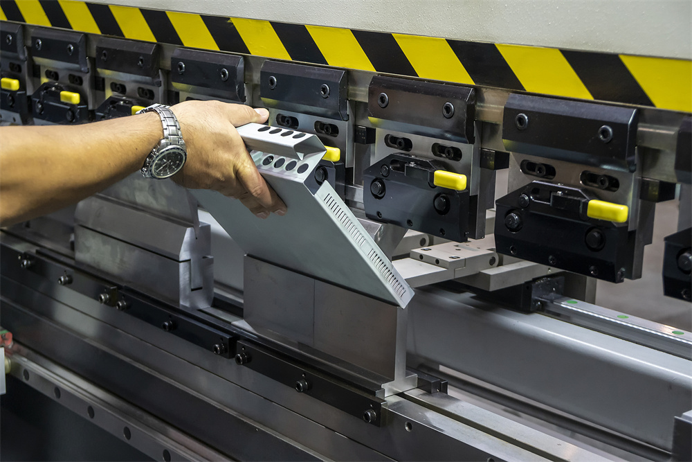
To perform a Press Brake Bend Allowance Bend Deduction: A Practical Calculation, one must first identify and measure several critical variables. These parameters form the foundation of every formula used in the shop. The most fundamental variable is Material Thickness (T). Even a slight variation in the actual thickness of the sheet metal compared to its nominal gauge can result in significant dimensional errors in the final product.
The second parameter is the Inside Bend Radius (R). In air bending, which is the most common method used on modern press brakes, the inside radius is not determined by the punch tip alone but is a function of the V-die width. Typically, the inside radius is approximately 15% to 17% of the V-opening width for cold-rolled steel. If the operator uses a different die than what was planned in the engineering stage, the bend allowance will change, leading to an inaccurate part.
The third critical factor is the Bend Angle (A). While 90-degree bends are the industry standard, many architectural and industrial components require obtuse or acute angles. The calculation must account for the specific degrees of the bend. Finally, we have the K-factor. The K-factor is a ratio that represents the location of the neutral axis relative to the material thickness. It typically ranges from 0.3 to 0.5. A K-factor of 0.5 means the neutral axis is exactly in the center of the material, which rarely happens in practice as the material tends to compress more than it stretches.
The Role of the Neutral Axis
The neutral axis is the key to understanding why metal expands. During a bend, the fibers on the outside of the radius are pulled apart, while the fibers on the inside are pushed together. The neutral axis is the transition zone where no tension or compression occurs. Its position shifts toward the inside of the bend as the radius becomes tighter relative to the thickness. Accurately predicting this shift is what allows a fabricator to calculate the exact amount of material needed.
Calculation Method: Step-by-Step Formulas
Calculating the flat length of a part involves either adding the Bend Allowance to the interior dimensions or subtracting the Bend Deduction from the exterior dimensions. Let’s break down the formulas used in Press Brake Bend Allowance Bend Deduction: A Practical Calculation.
1. Bend Allowance (BA) Formula
The Bend Allowance is the length of the arc along the neutral axis. The formula is:
BA = A × (π / 180) × (R + K × T)
Where:
A = Bend angle in degrees
R = Inside bend radius
K = K-factor
T = Material thickness
By calculating the BA, you can determine the flat length by adding the BA to the lengths of the flat sections (flanges) of the part, measured to the tangent points of the bend.
2. Outside Set Back (OSSB)
Before calculating Bend Deduction, you must find the Outside Set Back. This is the distance from the apex of the outside bend to the tangent point where the bend begins. For a 90-degree bend, the formula is simple:
OSSB = R + T.
For other angles, the formula is:
OSSB = tan(A / 2) × (R + T).
3. Bend Deduction (BD) Formula
The Bend Deduction is the amount of material you must subtract from the sum of the outside flange lengths to get the flat length. It is the most popular method in North America because outside dimensions are easier to measure on a finished part. The formula is:
BD = (2 × OSSB) – BA.
To find the total flat length using BD:
Flat Length = (Flange 1 + Flange 2) – BD.
Note that Flange 1 and Flange 2 are the exterior dimensions of the part.
Parameter Table: K-Factor and Material Reference
The following table provides a general guideline for K-factors based on the ratio of the inside radius (R) to the material thickness (T). These values are essential for accurate Press Brake Bend Allowance Bend Deduction: A Practical Calculation.
| R/T Ratio | K-Factor (Soft Materials) | K-Factor (Medium Materials) | K-Factor (Hard Materials) |
|---|---|---|---|
| 0.5 | 0.35 | 0.33 | 0.30 |
| 1.0 | 0.40 | 0.38 | 0.35 |
| 1.5 | 0.43 | 0.41 | 0.38 |
| 2.0 | 0.45 | 0.43 | 0.40 |
| 3.0+ | 0.50 | 0.48 | 0.45 |
It is important to note that these values are starting points. Real-world factors such as the grain direction of the steel, the hardness of the specific alloy, and the speed of the press brake stroke can all influence the actual K-factor. For high-precision work, HARSLE recommends performing a test bend on a scrap piece of the same material to reverse-calculate the exact K-factor for your specific setup.
Common Engineering Mistakes in Bending Calculations
Even with the correct formulas, errors can creep into the fabrication process. One of the most common mistakes is ignoring the Grain Direction of the metal. Sheet metal is rolled at the mill, creating a longitudinal grain. Bending with the grain (parallel) is easier but more prone to cracking and offers different stretching characteristics than bending against the grain (perpendicular). If your calculations don’t account for this, your parts may vary in length depending on how they were nested on the laser or plasma cutter.
Another frequent error is the Incorrect Inside Radius Assumption. Many engineers design parts with a specific radius in CAD, but the shop floor uses a V-die that produces a different radius. Since the radius is a primary component of both BA and BD formulas, this discrepancy leads to parts that are consistently out of tolerance. Always ensure that the engineering department and the shop floor are synchronized regarding the tooling being used.
Neglecting Material Thickness Variation is a third pitfall. A “10-gauge” sheet of steel can vary in thickness by several thousandths of an inch between batches. In precision electronics or aerospace applications, this variation is enough to throw off the bend deduction. Using a caliper to measure the actual thickness of the current batch and updating the CNC controller parameters is a best practice for high-accuracy shops.
Finally, many operators forget to account for Springback. While springback affects the angle of the bend rather than the flat length directly, the over-bending required to compensate for springback can slightly alter the final geometry. Advanced HARSLE press brakes utilize angle sensors and real-time compensation to mitigate this issue, ensuring that the physical result matches the mathematical calculation.
Selection Checklist: Ensuring Precision in Your Shop
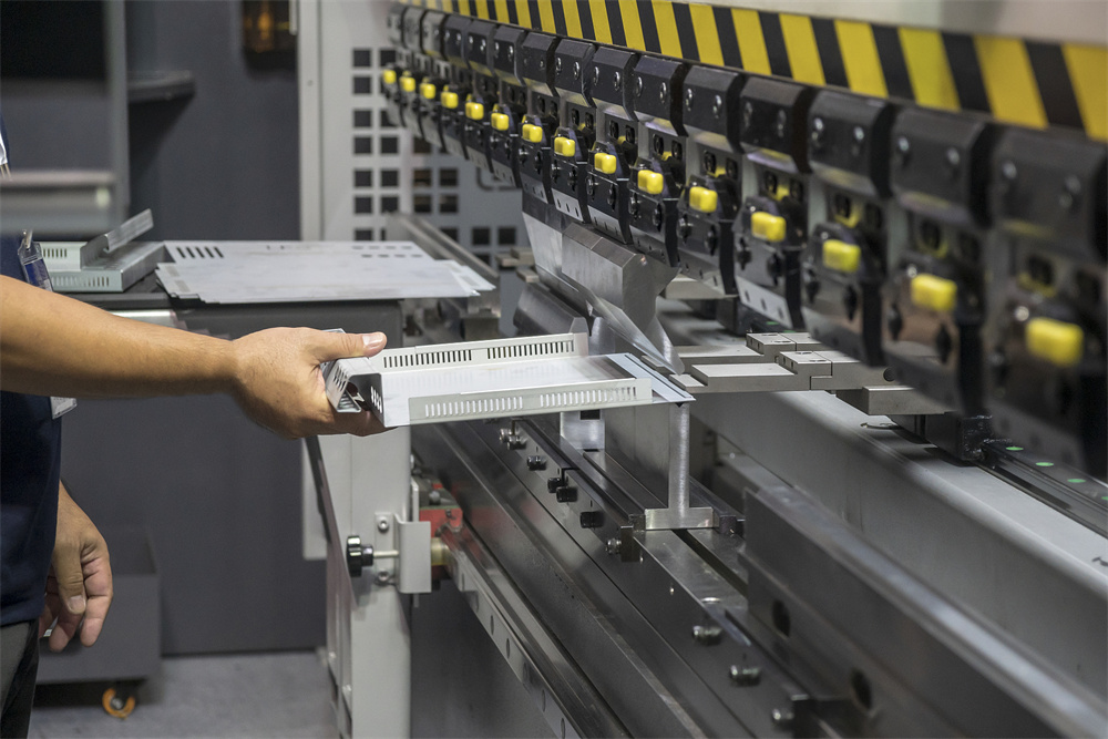
To achieve consistent results with Press Brake Bend Allowance Bend Deduction: A Practical Calculation, you need the right equipment and processes. Use this checklist to evaluate your current setup:
- Machine Calibration: Is your press brake calibrated for ram repeatability? Even a 0.01mm difference can affect the bend.
- Tooling Quality: Are you using precision-ground tooling? Worn dies change the effective inside radius, rendering your calculations obsolete.
- CNC Controller Capabilities: Does your controller (e.g., Delem, Cybelec, or ESA) support custom K-factor tables for different materials?
- Material Testing: Do you have a process for performing test bends and recording the results in a centralized database?
- Software Integration: Does your CAD/CAM software use the same bend deduction tables as your press brake controller?
- Operator Training: Do your operators understand the difference between air bending and bottoming, and how each affects the radius?
FAQ: Frequently Asked Questions
What is the difference between Bend Allowance and Bend Deduction?
Bend Allowance (BA) is the actual length of the material in the bend area (the arc). Bend Deduction (BD) is the amount of material ‘saved’ or subtracted from the total outside dimensions to account for the stretching of the metal. BD is generally more practical for manual measurement, while BA is often used in CAD unfolding.
How does the V-die width affect the calculation?
The V-die width determines the inside radius in air bending. A wider die creates a larger radius, which increases the Bend Allowance and changes the Bend Deduction. As a rule of thumb, the V-opening should be 8 times the material thickness for standard mild steel bending.
Can I use a K-factor of 0.44 for everything?
While 0.448 is a common default K-factor for many CAD programs, it is an average. Using it for very thick materials or very tight radii will result in errors. It is always better to use a material-specific K-factor from a verified table or through empirical testing.
Does the bend speed affect the bend deduction?
Generally, no. The bend deduction is a geometric property based on the final shape. However, very high speeds can cause some materials to behave differently due to heat or strain-rate sensitivity, but for standard industrial applications, speed is not a factor in the BA/BD calculation.
Why is my part too short even though I used the formula?
This usually happens because the actual inside radius produced by the machine is smaller than the radius used in the formula. Check your V-die and ensure the material isn’t ‘bottoming out’ in the die, which forces a tighter radius than air bending would.
By mastering the Press Brake Bend Allowance Bend Deduction: A Practical Calculation, fabricators can significantly reduce scrap, improve assembly fit-up, and increase the overall efficiency of their production line. Whether you are using a manual machine or a top-of-the-line HARSLE CNC press brake, the physics of the bend remain the same: precision starts with the math.