
How to Diagnose Press Brake Electrical Problems Before They Cause Downtime


Introduction to Electrical Reliability in Metal Fabrication
In the high-stakes world of metal fabrication, the press brake stands as a cornerstone of production. Whether you are bending complex aerospace components or simple structural brackets, the precision and uptime of your machine directly dictate your profitability. However, even the most robust machines, such as those engineered by HARSLE, are susceptible to the silent threat of electrical failure. To Diagnose Press Brake Electrical Problems Before They Cause Downtime is not just a maintenance task; it is a strategic necessity for any modern workshop.
Electrical systems in modern CNC press brakes are incredibly sophisticated, acting as the nervous system that coordinates hydraulic valves, backgauge motors, and safety light curtains. When a single relay fails or a wire becomes frayed due to years of vibration, the entire production line can grind to a halt. The cost of this downtime is multifaceted, encompassing lost labor hours, missed delivery deadlines, and potential damage to expensive tooling or workpieces. By implementing a proactive diagnostic framework, operators and maintenance technicians can identify the early warning signs of electrical fatigue before they manifest as a catastrophic failure.
This guide is designed to provide a deep dive into the methodologies required to monitor, identify, and resolve electrical issues. We will explore the common culprits of electrical instability, from power supply fluctuations to PLC logic errors, and provide actionable advice on how to keep your HARSLE press brake running at peak efficiency. Understanding the synergy between hardware and software is the first step in mastering the art of industrial machine maintenance.

Key Considerations for Electrical Diagnostics
Before diving into the technical minutiae, it is essential to establish a foundation of safety and systematic observation. Electrical troubleshooting on industrial machinery involves high-voltage circuits that can be lethal if handled improperly. Always adhere to Lockout/Tagout (LOTO) procedures before opening any electrical cabinets. The goal is to Diagnose Press Brake Electrical Problems Before They Cause Downtime without compromising the safety of the personnel involved.
The first consideration is the environment in which the press brake operates. Metal fabrication shops are notoriously harsh environments, filled with conductive metallic dust, fluctuating temperatures, and significant vibration. These factors are the primary drivers of electrical degradation. For instance, fine dust can settle on circuit boards, causing micro-shorts, while constant vibration can loosen terminal screws over time. A visual inspection should always be the first step: look for discolored wires (indicating overheating), smell for ozone or burnt plastic, and listen for unusual humming or clicking from the electrical cabinet.
Another critical factor is the quality of the incoming power supply. Many electrical “problems” are actually external to the machine. Voltage spikes or sags from the local grid can cause the CNC controller to reboot or throw cryptic error codes. If your shop shares a transformer with heavy equipment that draws high starting currents (like large plasma cutters or welding stations), your press brake may experience “dirty” power. Installing a power conditioner or a dedicated voltage regulator can often eliminate phantom electrical issues that are difficult to trace within the machine itself.
Finally, documentation is your most valuable tool. Every HARSLE machine comes with a comprehensive electrical schematic. Being able to read these diagrams is the difference between a quick fix and hours of guesswork. Technicians should be trained to trace circuits from the main breaker through the transformers, into the PLC, and out to the actuators. Keeping a log of every error code and the conditions under which it occurred will help identify patterns that point toward a specific failing component.
Technical Details: Component-Level Troubleshooting
The PLC and CNC Controller
The Programmable Logic Controller (PLC) is the brain of the press brake. It processes inputs from foot pedals and sensors and sends outputs to the hydraulic valves. When you need to Diagnose Press Brake Electrical Problems Before They Cause Downtime, the PLC’s diagnostic LEDs are a goldmine of information. Most PLCs have status lights for “Power,” “Run,” and “Error.” If the error light is flashing, the controller has detected an internal logic fault or a hardware mismatch. Modern CNC interfaces, like those found on HARSLE machines, will display specific alarm codes. Do not simply clear the alarm; investigate the root cause. For example, an “I/O Communication Error” often points to a loose ribbon cable or a failing bus module rather than a software glitch.
Sensors and Feedback Loops
Precision bending relies on feedback. Linear scales (encoders) on the Y1 and Y2 axes tell the controller exactly where the ram is located. If these sensors provide erratic data, the machine may tilt or stop mid-stroke. Electrical noise (EMI) is a common enemy here. Ensure that signal cables are shielded and routed away from high-voltage motor leads. If the machine loses its reference point frequently, check the mounting of the encoders and the integrity of the cables. A small break in the internal shielding can cause intermittent signals that are notoriously difficult to catch during a static inspection.
Contactors, Relays, and Solenoids
These are the mechanical-electrical interfaces of the machine. Contactors handle the high current required for the main pump motor, while smaller relays control auxiliary functions. Because they have moving parts, they have a finite lifespan. Pitting on the contact surfaces increases resistance, leading to heat and eventual failure. If you hear a “chattering” sound when the motor starts, the contactor is likely failing. Similarly, hydraulic solenoid valves can fail electrically (burnt coil) or mechanically (stuck plunger). Using a multimeter to check the resistance of the solenoid coil can quickly confirm if the electrical component is still within its operating specifications.
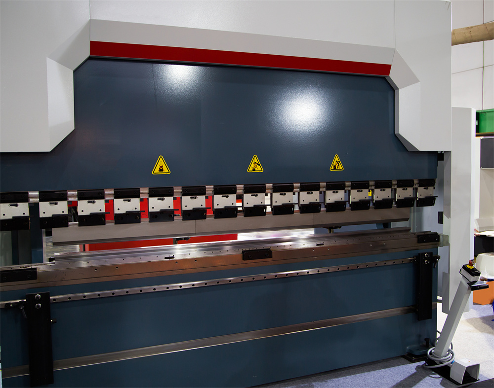
Wiring and Terminations
It is estimated that over 50% of industrial electrical failures are caused by poor connections. Thermal expansion and contraction, combined with machine vibration, can cause wires to back out of their terminals. This creates a high-resistance connection that generates heat, further damaging the wire insulation. During scheduled maintenance, a “tug test” on critical wires and the use of an infrared thermal camera to spot “hot spots” in the electrical cabinet can prevent a fire or a sudden breakdown. Pay special attention to the ground bus; a poor ground can cause erratic behavior across the entire electronic system.
| Component | Common Symptom | Diagnostic Action |
|---|---|---|
| Main Motor Contactor | Motor fails to start or hums loudly | Check for pitted contacts and coil voltage |
| Linear Encoders | Ram parallelism errors (Y1/Y2 mismatch) | Inspect cable shielding and clean scale glass |
| 24V Power Supply | CNC screen flickers or PLC resets | Measure DC output stability under load |
| Foot Pedal Switch | No response when pedal is pressed | Test continuity of the internal microswitches |
| Emergency Stop Circuit | Machine won’t reset from E-stop state | Check for stuck buttons or broken safety relays |
Selection Advice: Choosing Machines with Superior Electrical Design
When purchasing new equipment, the ability to Diagnose Press Brake Electrical Problems Before They Cause Downtime is largely determined by the machine’s original design and component selection. HARSLE prioritizes the use of world-class electrical components from brands like Schneider, Siemens, and ABB. This is not just for brand recognition; these components are designed for the rigors of industrial use and offer better diagnostic features, such as built-in status indicators and modular designs that allow for quick replacement.
Look for machines that feature well-organized electrical cabinets. A “spaghetti” of wires makes troubleshooting nearly impossible. A high-quality press brake will have clearly labeled wires that correspond to the electrical schematic, neatly routed in wire ducts. Furthermore, the cabinet should be properly ventilated or even air-conditioned if the machine is intended for use in hot climates. Heat is the number one killer of electronics; a machine that runs cool will inherently have fewer electrical failures over its lifespan.
Another aspect to consider is the accessibility of the I/O (Input/Output) modules. In a well-designed system, a technician can quickly probe the I/O points to see if a signal is reaching the PLC. If the machine uses a proprietary, closed-box controller with no external diagnostics, you will be entirely dependent on the manufacturer for every minor repair. HARSLE’s use of open-architecture or widely supported CNC systems (like Delem or Cybelec) ensures that you have the tools and the local support needed to handle diagnostics in-house.
Finally, consider the safety integration. Modern machines use dedicated safety PLC modules rather than just a string of series-wired E-stop buttons. These safety controllers provide specific feedback on which safety device has been triggered or has failed. This level of detail significantly reduces the time spent chasing a “safety loop open” error, allowing your team to get back to production faster.
Frequently Asked Questions (FAQ)
How often should I inspect the electrical cabinet of my press brake?
A thorough visual inspection should be performed monthly. This includes checking for dust buildup, ensuring cooling fans are operational, and looking for any signs of heat damage. A more technical inspection, including tightening terminals and checking voltages, should be part of your semi-annual preventative maintenance routine.
Why does my press brake throw an error code only when it gets hot in the afternoon?
This is a classic sign of thermal instability. As components heat up, their electrical resistance changes. A marginal component (like a failing power supply or a weak relay) might work fine at 70°F but fail at 100°F. Check the cabinet filters and fans. If the cabinet is getting too hot, you may need to install an active cooling unit.
Can I replace a faulty relay with any brand as long as the voltage matches?
While it might work in an emergency, it is highly recommended to use the exact replacement part specified by the manufacturer. Different brands may have different response times, contact materials, or inductive load ratings. Using the wrong relay can lead to premature failure or even damage the PLC output that drives it.
What is the most common cause of CNC controller lockups?
The most common cause is “dirty” power or electromagnetic interference (EMI). Ensure the machine is properly grounded to a dedicated ground rod and that high-voltage cables are not running parallel to sensitive data cables. If the problem persists, a dedicated UPS (Uninterruptible Power Supply) for the controller can help stabilize the logic voltage.
Is it safe to use compressed air to clean the electrical cabinet?
No, using standard shop air is dangerous for electronics. Shop air often contains moisture and oil, which can create conductive paths on circuit boards. Additionally, the high pressure can force metallic dust deeper into sensitive components. Use a specialized vacuum designed for electronics or cans of clean, dry electronic duster air.
Conclusion: The Path to Zero Downtime
The ability to Diagnose Press Brake Electrical Problems Before They Cause Downtime is a skill that pays dividends every day. By shifting from a reactive “fix it when it breaks” mindset to a proactive diagnostic approach, you protect your investment and ensure the reliability of your production schedule. The electrical system of a HARSLE press brake is designed for longevity, but it requires the watchful eye of a trained operator and a disciplined maintenance program to reach its full potential.
Remember that diagnostics is a process of elimination. Start with the simplest possibilities—fuses, loose wires, and power supply—before moving to complex logic or hydraulic issues. Invest in the right tools, such as high-quality multimeters and thermal imagers, and ensure your team is fluent in reading electrical schematics. When you understand the language of your machine’s electrical system, you gain the power to predict the future, turning potential disasters into routine, manageable maintenance tasks.
Ultimately, the goal is to keep the ram moving and the parts flowing. A well-maintained electrical system is the foundation of that goal. By following the principles outlined in this guide, you can minimize the risk of unexpected stops and maximize the efficiency of your metal fabrication operations for years to come.

