A Practical Guide to Laser Cutting Machine Nozzle Selection and Focus Settings


Technical Overview
In the realm of modern metal fabrication, the precision of a laser cutting machine is not merely a product of its power source or CNC controller. It is fundamentally dictated by the interaction between the laser beam, the assist gas, and the workpiece. Achieving high-quality cuts requires a deep understanding of the nozzle and the focal position. As a leading manufacturer of metal fabrication equipment, HARSLE emphasizes that the nozzle acts as the final interface between the machine’s internal optics and the external environment, shaping the gas flow and protecting the lens.
The nozzle design—specifically its diameter and geometry—determines the gas flow rate and the pressure distribution across the cut kerf. When the nozzle is correctly selected, it ensures that the assist gas effectively removes molten material while cooling the surrounding heat-affected zone (HAZ). Conversely, an incorrect nozzle choice can lead to turbulence, poor edge quality, and increased dross formation, which compromises the integrity of the finished part.
Focus settings, on the other hand, define where the laser beam’s energy density is at its peak relative to the material thickness. The focal point is the narrowest part of the beam, and its position—whether on the surface, inside the material, or above the surface—drastically alters the cutting dynamics. For thin sheets, a positive focus might be preferred, while thicker plates often require a negative focus to ensure the beam penetrates the full depth of the material.
At HARSLE, we observe that many operators struggle with the balance between these two variables. A common misconception is that a single setting can be applied across all material types and thicknesses. In reality, the synergy between nozzle diameter and focal position is dynamic. This guide aims to demystify these technical parameters, providing a roadmap for operators to achieve consistent, high-precision results in their daily production cycles.
Core Parameters
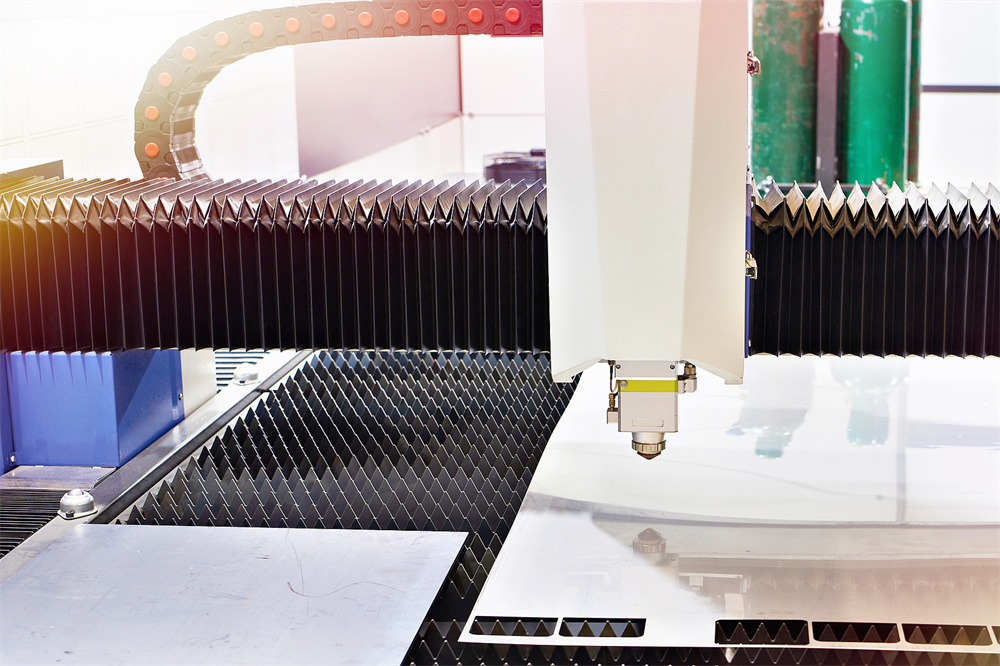
The nozzle diameter is the primary factor influencing the gas flow volume. Standard nozzles typically range from 0.8mm to 3.0mm. A smaller nozzle diameter is generally used for thin materials with high-pressure nitrogen, as it creates a high-velocity gas stream that effectively clears the kerf without excessive gas consumption. For thicker materials, larger nozzle diameters are necessary to accommodate the higher volume of oxygen or nitrogen required to blow away molten metal from deep cuts.
Focal position, or the ‘Z-axis’ offset, is the second critical parameter. The focal point is where the laser beam diameter is smallest and power density is highest. When the focal point is set exactly on the surface of the workpiece, the beam is most effective for engraving or marking. However, for cutting, the focal point is usually shifted. A ‘negative focus’ (below the surface) is often used for thick stainless steel or carbon steel to ensure the beam energy remains concentrated throughout the thickness of the plate.
The assist gas pressure is intrinsically linked to the nozzle and focus. If the nozzle diameter is too large for the pressure being applied, the gas flow becomes turbulent, leading to inconsistent cutting. Conversely, if the pressure is too low for the nozzle size, the gas will not have enough kinetic energy to eject the molten metal, resulting in dross buildup at the bottom of the cut. Balancing these three elements—nozzle size, focal position, and gas pressure—is the hallmark of an expert operator.
Another vital parameter is the nozzle-to-workpiece distance, often called the ‘standoff distance.’ This distance is typically maintained by the machine’s capacitive height sensing system. If the nozzle is too close, it risks collision with the material, especially if the sheet is warped. If it is too far, the gas flow loses its focus and velocity, leading to poor cutting quality. Maintaining a consistent standoff distance is essential for the stability of the cutting process.
Calculation Method
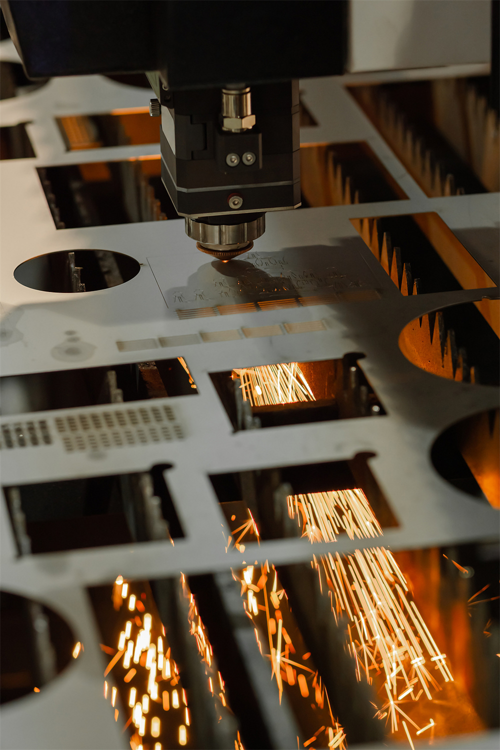
Calculating the optimal settings for a new material involves a systematic approach. First, identify the material type and thickness. For carbon steel, oxygen is typically used as the assist gas, which aids the cutting process through an exothermic reaction. For stainless steel and aluminum, nitrogen is used to prevent oxidation and ensure a clean, bright edge. The nozzle diameter should be selected based on the thickness: thin materials (1-3mm) perform best with 1.0mm-1.5mm nozzles, while thicker materials (6mm+) require 2.0mm-3.0mm nozzles.
To determine the focal position, start with the manufacturer’s recommended baseline. If the cut edge shows excessive dross at the bottom, the focal point may be too high. Lowering the focal point (moving it deeper into the material) can often resolve this. If the top edge of the cut is rounded or melted, the focal point might be too low, or the power density is too high for the feed rate. Adjusting the focal position in 0.5mm increments is a standard practice for fine-tuning.
The relationship between nozzle diameter and gas pressure can be calculated using the flow rate formula. As the nozzle diameter increases, the area of the orifice increases by the square of the radius. Therefore, doubling the nozzle diameter requires a significant increase in gas pressure to maintain the same velocity. Operators should consult the HARSLE technical manual for specific flow rate charts, as these are calibrated for the specific laser head geometry of the machine.
Finally, perform a ‘test cut’ on a scrap piece of the same material. Examine the kerf width and the smoothness of the cut surface. A high-quality cut will have a narrow, uniform kerf with minimal striations. If the striations are deep and angled, it indicates that the feed rate is too high for the current focal position or gas pressure. By iterating through these adjustments, operators can build a custom ‘cutting library’ for their specific production needs.
Parameter Table
| Material Type | Thickness (mm) | Nozzle Diameter (mm) | Focal Position (mm) | Assist Gas |
|---|---|---|---|---|
| Carbon Steel | 1-3 | 1.2 – 1.5 | 0 to +1 | Oxygen |
| Carbon Steel | 6-12 | 1.8 – 2.0 | -1 to -3 | Oxygen |
| Stainless Steel | 1-3 | 1.0 – 1.2 | 0 to -1 | Nitrogen |
| Stainless Steel | 6-10 | 1.5 – 2.0 | -2 to -4 | Nitrogen |
| Aluminum | 2-5 | 1.5 – 1.8 | -1 to -2 | Nitrogen |
Common Engineering Mistakes
One of the most frequent mistakes is neglecting nozzle maintenance. Over time, the nozzle orifice can become deformed due to heat or physical contact with the workpiece. A damaged nozzle creates an asymmetrical gas flow, which causes the laser beam to be deflected, resulting in slanted cuts or inconsistent edge quality. Operators should inspect the nozzle daily and replace it if there are any signs of wear or slag buildup.
Another common error is using the wrong gas purity. For nitrogen cutting, purity levels must be at least 99.99%. If the nitrogen is contaminated with oxygen, the cut edge will show discoloration and oxidation, defeating the purpose of using nitrogen. Similarly, using low-quality oxygen can lead to impurities in the cut, making it difficult to weld or paint the part later. Always ensure that your gas supply system is filtered and free of moisture or oil.
Ignoring the calibration of the capacitive height sensor is a critical oversight. If the sensor is not calibrated, the machine may not maintain the correct standoff distance, leading to nozzle crashes or poor cutting performance. Regular calibration, especially after changing the nozzle or the protective lens, is essential for maintaining the accuracy of the laser cutting machine.
Finally, many operators fail to adjust their cutting parameters when switching between different batches of material. Even within the same grade, variations in material composition or surface finish can affect the laser’s absorption. Always perform a quick test cut when starting a new batch of material to ensure that the nozzle and focus settings are still optimal for the current conditions.
Selection Checklist
- Material Compatibility: Does the nozzle material (usually copper) match the heat requirements of the metal being cut?
- Nozzle Geometry: Is the nozzle a single-layer or double-layer design? (Single-layer for high-pressure nitrogen, double-layer for oxygen).
- Orifice Integrity: Is the nozzle free of slag, scratches, or deformation?
- Gas Flow Consistency: Have you verified the gas pressure at the nozzle tip, not just at the regulator?
- Focal Range: Does the machine’s autofocus system have the range required for the material thickness?
- Lens Cleanliness: Is the protective lens clean? A dirty lens will scatter the beam, rendering nozzle and focus settings ineffective.
- Standoff Distance: Is the height sensor calibrated to the specific nozzle being used?
FAQ
Q: How often should I replace my laser nozzle?
A: There is no set time, but you should replace it whenever you notice a decline in cut quality, slag buildup, or if the nozzle has been involved in a collision. Daily inspection is recommended.
Q: Why is my stainless steel cut edge turning yellow?
A: This is usually due to nitrogen contamination or insufficient gas pressure. Check your nitrogen purity and ensure the nozzle diameter is appropriate for the thickness.
Q: Can I use the same nozzle for both carbon steel and stainless steel?
A: While technically possible, it is not recommended. Carbon steel typically uses oxygen with double-layer nozzles, while stainless steel uses nitrogen with single-layer nozzles for better flow dynamics.
Q: How does the focal position affect the kerf width?
A: A focal position that is too far from the material surface will result in a wider, less precise kerf. Keeping the focal point optimized ensures the narrowest possible kerf and the highest precision.
Q: What should I do if the nozzle keeps hitting the material?
A: Check the material flatness, ensure the height sensor is calibrated, and verify that the nozzle-to-workpiece distance is set correctly in the software. If the material is warped, consider using a sheet leveling system.