Press Brake Crowning Explained: Improving Bend Consistency Across the Sheet


Technical Overview: The Physics of Deflection and the Need for Crowning
In the world of precision metal fabrication, achieving a perfectly uniform bend across the entire length of a long sheet is one of the most significant challenges. When a press brake applies several hundred tons of force to a workpiece, the machine itself is subject to the laws of physics. Specifically, the upper beam (ram) and the lower bed (table) experience deflection. Because the hydraulic cylinders are typically located at the ends of the machine, the center of the beam and bed tend to bow away from each other. This phenomenon is colloquially known as the ‘canoe effect.’
Without a compensation mechanism, the resulting part will have a ‘shallow’ angle in the middle and a ‘tight’ angle at the ends. For example, if you are aiming for a 90-degree bend, you might find the ends are exactly 90 degrees, but the center is 92 or 93 degrees. Press brake crowning is the engineered solution to this problem. It involves intentionally creating a counter-curve in either the bed or the ram to offset the natural deflection caused by bending forces. By ensuring that the punch and die remain parallel under load, crowning allows for consistent angles from one end of the sheet to the other.
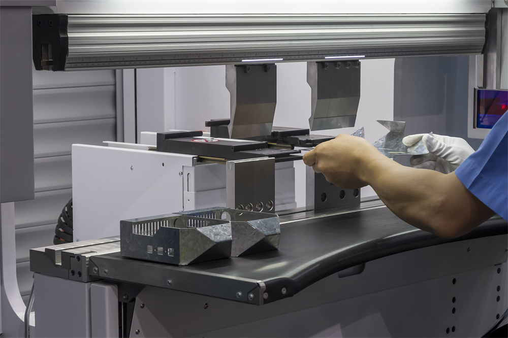
There are two primary types of crowning systems used in modern HARSLE machinery: Hydraulic and Mechanical. Hydraulic crowning utilizes a series of cylinders built into the lower worktable. As the bending pressure increases, the CNC controller activates these cylinders to push the center of the bed upward. Mechanical crowning, on the other hand, uses a series of sliding wedges (often referred to as a Wila-style system) that create a physical curve in the table. Both systems aim to achieve the same result: a perfectly straight bend line regardless of the material length or thickness.
Understanding crowning is essential for any operator or engineer working with high-tensile materials or long parts. As tolerances in industries like aerospace, automotive, and heavy infrastructure become tighter, the ability to manage machine deflection through precise crowning becomes a competitive advantage. It reduces scrap, eliminates the need for manual shimming, and significantly speeds up setup times for complex jobs.
Core Parameters Influencing Crowning Requirements
To effectively manage crowning, one must understand the variables that dictate how much deflection will occur. The first and most obvious parameter is Material Length. The longer the bend, the more pronounced the deflection will be. A 1-meter bend on a 4-meter machine may require negligible crowning, whereas a full-length 4-meter bend will require significant compensation. This is because the distance between the main hydraulic cylinders acts as a span, and like any bridge or beam, a longer span deflects more under a central load.
Material Thickness and Tensile Strength are equally critical. Bending a 10mm plate of Hardox or high-strength stainless steel requires significantly more tonnage than bending 2mm mild steel. Higher tonnage translates directly to higher deflection forces. The crowning system must be robust enough to counteract these forces. If the material’s yield strength varies—which is common in different batches of steel—the crowning system must be adjustable to compensate for these fluctuations in real-time or through operator intervention.
The V-Die Opening also plays a role. A narrower V-die requires more tonnage to achieve a bend, which increases deflection. Conversely, a wider V-die reduces the required tonnage but may change the radius of the bend. Operators must balance the choice of tooling with the machine’s crowning capabilities. In a CNC-controlled environment, the controller typically calculates the required crowning based on the entered material type, thickness, length, and tooling data.
Finally, the Machine’s Structural Integrity is a baseline parameter. Older machines or those with lighter frames will deflect more than heavy-duty, high-rigidity frames like those found in HARSLE’s premium series. The ‘stiffness’ of the press brake determines the baseline deflection curve that the crowning system must overcome. Understanding these parameters allows engineers to predict bending behavior and set up the machine for ‘first-part, right-part’ production.
Calculation Method: Determining the Compensation Value
The calculation of crowning is rooted in structural engineering formulas for beam deflection. The most basic representation of this is the formula for a simply supported beam with a distributed load: δ = (5wL⁴) / (384EI), where δ is the deflection, w is the load per unit length, L is the length, E is the Modulus of Elasticity, and I is the Moment of Inertia. While operators don’t calculate this manually on the shop floor, the CNC controller uses similar algorithms to estimate the ‘bow’ in the bed.
In modern CNC systems, the process is automated. The operator inputs the material parameters (Yield Strength, Thickness, Length) and the Tooling parameters (V-width, Punch Radius). The controller then references a pre-installed deflection table specific to that machine model. It calculates the expected tonnage and, subsequently, the required crowning value (usually expressed in millimeters or as a percentage of maximum crowning capacity).
For manual machines or those without integrated CNC crowning, operators often use a ‘trial and error’ approach combined with shimming. However, a more scientific manual method involves performing a test bend on a long strip of the target material. By measuring the angle at the ends versus the center, the operator can determine the angular deviation. For every degree of deviation, a specific amount of crowning (often 0.1mm to 0.3mm depending on the V-die) is added. This manual adjustment is then recorded for future setups of the same material.
Advanced systems now incorporate Real-Time Angle Measurement. These systems use lasers or contact sensors to measure the bend angle as it happens. If the sensors detect that the center is under-bending, the CNC can dynamically increase the crowning pressure during the stroke. This closed-loop system is the pinnacle of crowning technology, ensuring perfect results even when material properties are inconsistent across the sheet.
Parameter Table: Typical Crowning Values for Mild Steel
The following table provides estimated crowning compensation values for standard mild steel (approx. 450 MPa tensile strength) on a standard 3200mm press brake. Note: These are reference values; actual requirements depend on machine rigidity and specific material batches.
| Material Thickness (mm) | V-Die Opening (mm) | Bend Length (mm) | Required Tonnage (Est.) | Crowning Compensation (mm) |
|---|---|---|---|---|
| 2.0 | 16 | 3000 | 45 Tons | 0.15 – 0.25 |
| 4.0 | 32 | 3000 | 90 Tons | 0.35 – 0.50 |
| 6.0 | 50 | 3000 | 135 Tons | 0.60 – 0.85 |
| 8.0 | 63 | 3000 | 180 Tons | 0.90 – 1.20 |
| 10.0 | 80 | 3000 | 220 Tons | 1.30 – 1.60 |
| 12.0 | 100 | 3000 | 270 Tons | 1.70 – 2.10 |
As seen in the table, as thickness and tonnage increase, the required compensation grows exponentially. It is also important to note that using a V-die that is too small for the thickness will spike the tonnage and require significantly more crowning, potentially exceeding the machine’s compensation limits.
Common Engineering Mistakes in Crowning Management
One of the most frequent mistakes in metal fabrication is Over-Crowning. This occurs when the operator or the CNC applies too much compensation, resulting in a ‘frown’ effect. In this scenario, the bend angle in the center of the sheet is tighter (e.g., 88 degrees) than at the ends (90 degrees). Over-crowning can be just as detrimental to part quality as under-crowning, especially in assemblies where straight edges are required for welding or interlocking.
Another common error is Inconsistent Shimming. In shops using older machines without automatic crowning, operators often place strips of paper or thin metal shims under the die to manually ‘crown’ the bed. While effective in a pinch, shimming is imprecise and time-consuming. It also creates ‘hard spots’ that can damage the bed or the tooling over time. Relying on shimming instead of investing in a proper crowning system leads to significant hidden costs in labor and wasted material.
Ignoring Material Grain Direction is a subtle but impactful mistake. Sheet metal has a grain resulting from the rolling process at the mill. Bending with the grain requires less force but is more prone to cracking, while bending against the grain requires more force. If a large sheet has parts nested in different orientations, the crowning requirement may change from one bend to the next. High-end CNC controllers can account for this if the grain direction is programmed into the job.
Finally, Poor Maintenance of the Crowning System can lead to inconsistent results. For hydraulic systems, air in the lines or degraded seals can cause the crowning cylinders to respond sluggishly or unevenly. For mechanical systems, dust and metal shavings can migrate into the wedge mechanism, causing it to bind. Regular cleaning and calibration are essential to ensure that the physical movement of the bed matches the values commanded by the CNC.
Selection Checklist: Choosing the Right Crowning System
When purchasing a new HARSLE press brake or retrofitting an existing one, consider the following checklist to ensure you select the most effective crowning solution for your needs:
- Workpiece Length: If you primarily bend parts under 2 meters, a basic crowning system may suffice. For parts 3 meters and longer, a high-precision CNC-controlled system is mandatory.
- Material Variety: Do you switch between aluminum, mild steel, and stainless steel frequently? If so, a CNC mechanical crowning system (Wila-style) is often preferred for its speed and repeatability across different material types.
- Tonnage Requirements: High-tonnage applications (over 200 tons) put immense stress on the bed. Ensure the crowning system is rated for the maximum tonnage of the machine to avoid mechanical failure.
- Integration with CNC: Ensure the crowning system is fully integrated with the machine’s controller (e.g., Delem, Cybelec, or ESA). This allows for automatic calculations and reduces operator error.
- Accuracy Requirements: For general fabrication, a standard hydraulic system is usually sufficient. For high-precision work (e.g., electronics enclosures or medical equipment), look for systems with fine-increment mechanical wedges.
- Maintenance Access: Choose a system where the crowning components are protected from debris but remain accessible for periodic maintenance and lubrication.
- Budget vs. ROI: While CNC mechanical crowning is more expensive upfront than hydraulic crowning, the reduction in setup time and scrap often results in a faster Return on Investment (ROI) for high-volume shops.
Frequently Asked Questions (FAQ)
1. Can I add a crowning system to an old press brake?
Yes, it is possible to retrofit many older press brakes with a manual or motorized mechanical crowning table. These units sit on top of the existing bed and provide a new mounting surface for the dies. However, integrating this with an old CNC controller can be complex and may require a control system upgrade.
2. Why is my press brake ‘frowning’ even with the crowning turned off?
If a machine produces a tighter angle in the middle without any crowning applied, it may indicate that the bed or ram has been permanently deformed (upset) due to overloading in the center. It could also mean the machine was not leveled correctly during installation. Professional calibration is required to diagnose and fix this issue.
3. Is hydraulic or mechanical crowning better?
Both have advantages. Hydraulic crowning is cost-effective and reacts well to the machine’s internal pressures. Mechanical crowning is generally considered more precise and consistent because it is not affected by oil temperature or hydraulic seal wear. Most high-end precision shops prefer mechanical crowning.
4. How often should I calibrate my crowning system?
For high-precision environments, crowning calibration should be checked monthly. For general fabrication, a quarterly check is usually sufficient. You should also recalibrate after any major event, such as a tool crash or when switching to a significantly different type of material.
5. Does crowning affect the backgauge accuracy?
Indirectly, yes. If the bed is significantly crowned (bowed upward), the relationship between the die and the backgauge fingers can change slightly. High-quality crowning systems are designed to minimize this shift, but operators should always verify backgauge positions when using extreme crowning values.