Comprehensive Guide: How to Maintain Hydraulic Systems in a Press Brake Machine


Technical Overview of Press Brake Hydraulic Systems
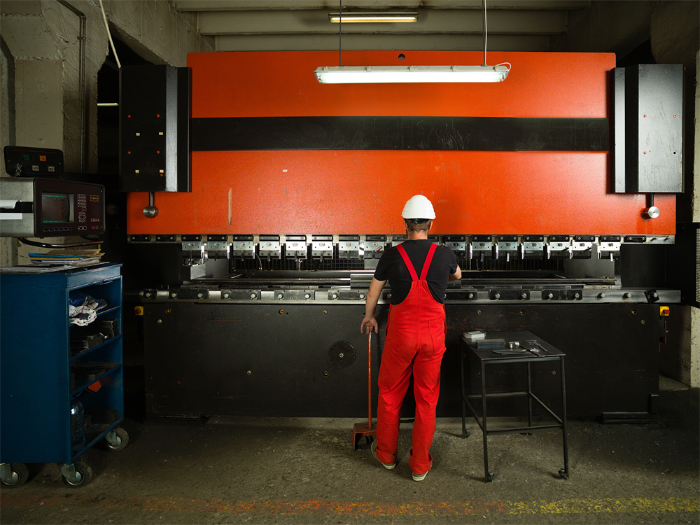
The hydraulic system is the heart of any modern press brake machine. It is responsible for converting electrical energy from the motor into mechanical force through the medium of pressurized fluid. To effectively maintain hydraulic systems in a press brake machine, one must first understand the architecture of these systems. Typically, a press brake utilizes a high-pressure pump (often a piston or internal gear pump) to draw oil from a reservoir and deliver it through a series of proportional valves to the main cylinders. These cylinders then drive the ram downward with precise force and synchronization.
In high-end CNC press brakes, such as those manufactured by HARSLE, the hydraulic system is often a closed-loop configuration. This means the system uses feedback from linear encoders to adjust the flow of oil in real-time, ensuring that the ram remains perfectly level even under off-center loading. The complexity of these systems—incorporating servo-valves, pressure transducers, and sophisticated manifold blocks—demands a rigorous maintenance schedule. Neglecting the hydraulic health of the machine leads to more than just leaks; it results in a loss of angular precision, increased cycle times, and eventually, catastrophic component failure.
Maintenance is not merely about fixing what is broken; it is about preserving the chemical and physical properties of the hydraulic fluid and the integrity of the mechanical seals. Contamination is the primary enemy of hydraulic systems. Microscopic particles, often invisible to the naked eye, can act as abrasives, wearing down the precision-ground surfaces of spool valves and pump internals. Therefore, a technical approach to maintenance focuses heavily on cleanliness, temperature control, and pressure regulation.
Core Parameters for Hydraulic Maintenance
When you aim to maintain hydraulic systems in a press brake machine, you must monitor several critical parameters. The first is oil viscosity. Most industrial press brakes require ISO VG 46 or ISO VG 32 hydraulic oil. Viscosity affects the lubricity and the internal friction of the system. If the oil is too thick, the pump may cavitate; if it is too thin, internal leakage increases, reducing the machine’s efficiency and causing the ram to ‘drift’ during the bending process.
The second parameter is operating temperature. The ideal temperature range for hydraulic oil in a press brake is between 35°C and 55°C (95°F to 131°F). When temperatures exceed 60°C, the oxidation process of the oil accelerates rapidly, leading to the formation of sludge and varnish. This sticky residue can cause valves to stick or respond sluggishly. Conversely, operating a machine in a cold environment without a pre-heat cycle can damage the pump due to the high resistance of cold, viscous oil.
Thirdly, filtration levels are paramount. Hydraulic systems are rated by NAS or ISO cleanliness codes. For a CNC press brake with proportional valves, a cleanliness level of ISO 18/16/13 is often required. This means the oil must be filtered through high-efficiency elements, typically rated at 10 microns or finer. Monitoring the pressure drop across the filter housing is a standard way to determine when a filter element needs replacement before it goes into bypass mode and allows contaminants to circulate freely.
Calculation Method for Hydraulic Performance
To maintain the system scientifically, engineers often need to calculate specific performance metrics. One of the most common calculations is determining the required pressing force (Tonnage) and ensuring the hydraulic system is delivering it. The formula for force is F = P × A, where F is the force in Newtons, P is the pressure in Pascals (N/m²), and A is the effective area of the cylinder piston in square meters.
For maintenance purposes, calculating the oil change interval is also vital. While many manuals suggest a flat 2,000 to 4,000 hours, a more accurate calculation involves the ‘Duty Cycle Factor’. If a machine is running 24/7 at maximum tonnage, the oil degrades faster. The formula used by some maintenance managers is: Actual Interval = Base Interval × (Operating Temp Factor) × (Contamination Factor). If the machine consistently runs 10°C above the recommended temperature, the oil life is effectively halved.
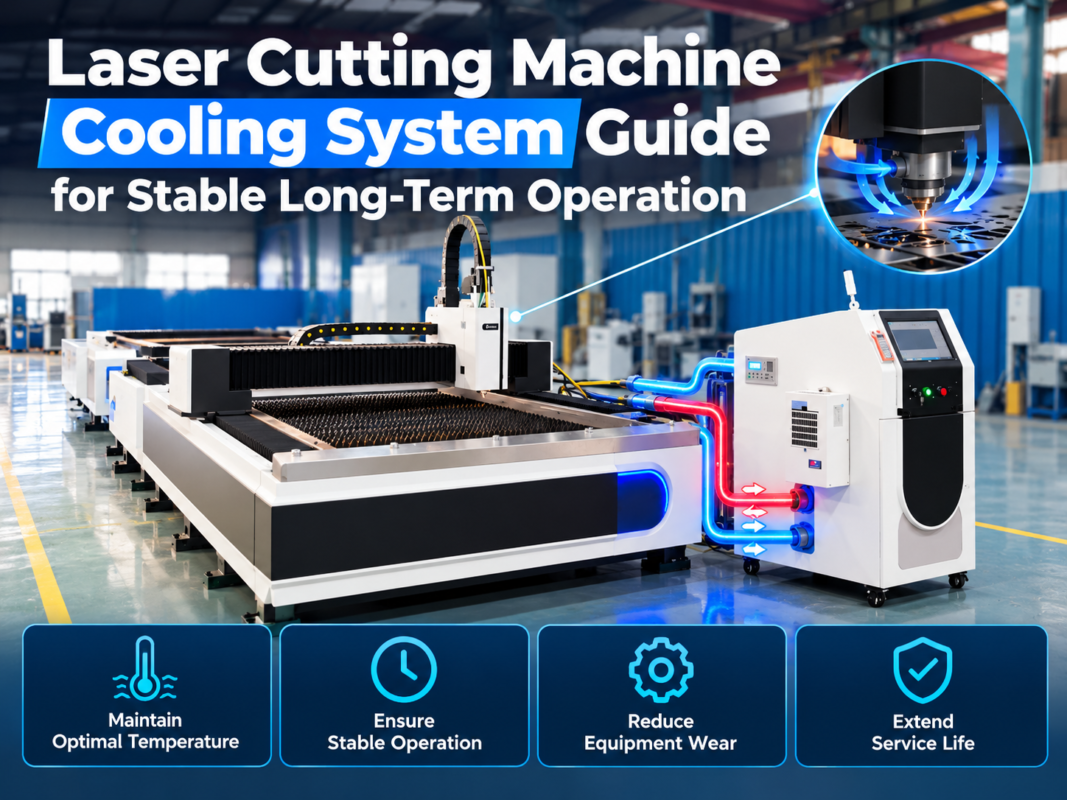
Another important calculation is the ‘Heat Load’. If the hydraulic system is overheating, you may need to calculate if the cooling system (air or water-cooled) is sufficient. The heat generated is roughly 20-30% of the input motor power. For a 15kW motor, the cooling system must be able to dissipate approximately 3kW to 4.5kW of heat to maintain a stable operating temperature. If the math doesn’t add up, it indicates a need for a larger heat exchanger or an investigation into internal leakage causing excessive friction.
Hydraulic System Parameter Table
The following table provides a reference for standard hydraulic parameters across different sizes of press brake machines. These values are typical for HARSLE equipment and should be used as a baseline for maintenance checks.
| Machine Tonnage (T) | Oil Tank Capacity (L) | Standard Oil Type | Max System Pressure (Bar) | Filter Rating (Micron) | Recommended Change Interval (Hrs) |
|---|---|---|---|---|---|
| 40T – 63T | 150 – 200 | ISO VG 46 | 250 | 10 – 20 | 2500 |
| 80T – 125T | 250 – 400 | ISO VG 46 | 280 | 10 | 2000 |
| 160T – 250T | 500 – 800 | ISO VG 46 | 300 | 5 – 10 | 2000 |
| 300T – 500T | 1000+ | ISO VG 46 | 320 | 5 | 1500 |
Common Engineering Mistakes in Hydraulic Maintenance
One of the most frequent mistakes when trying to maintain hydraulic systems in a press brake machine is the improper handling of hydraulic oil. Many operators top off the oil tank using a dirty funnel or directly from a drum that has been sitting open. New oil is not necessarily clean oil; it often contains high levels of moisture and particulates from the refining and barreling process. Always use a filtration cart to pump new oil into the machine’s reservoir.
Another common error is the over-tightening of hydraulic fittings. When a small leak is spotted, the instinct is to crank down on the nut. However, most modern press brakes use JIC or O-ring face seal (ORFS) fittings. Over-tightening these can deform the flare or crush the O-ring, leading to a much larger leak that requires component replacement. The correct approach is to depressurize the system, inspect the seal, and replace it if necessary, then torque to the manufacturer’s specification.
Ignoring the ‘sound’ of the machine is a subtle but costly mistake. Cavitation—the formation and collapse of vapor bubbles in the oil—produces a distinct high-pitched whining or ‘marbles in a blender’ sound. This is often caused by a clogged suction strainer or a leak in the intake line. If left unaddressed, cavitation will pit the internal surfaces of the pump, leading to total pump failure within hours of operation. Maintenance teams should be trained to recognize these acoustic warnings early.
Selection Checklist for Hydraulic Components and Tools
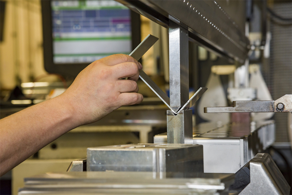
When performing maintenance or replacing parts, use this checklist to ensure you are selecting the right components for your press brake:
- Seal Compatibility: Ensure replacement seals are made of Nitrile (NBR) for standard use or Viton (FKM) for high-temperature environments. Never mix seal materials within a single cylinder.
- Filter Efficiency: Look for the ‘Beta Ratio’ on filter elements. A Beta ratio of β10 ≥ 200 means the filter captures 99.5% of 10-micron particles. Avoid ‘nominal’ rated filters which are less efficient.
- Pressure Gauges: Use glycerin-filled gauges for permanent installation to dampen vibration and provide accurate readings. Ensure the gauge range is 1.5x the maximum system pressure.
- Hydraulic Oil: Select a premium anti-wear (AW) hydraulic oil from a reputable brand. Check for additives that prevent foaming and improve water separation (demulsibility).
- Hose Assemblies: When replacing hoses, check the SAE rating. A 4-wire spiral hose (SAE 100R12) is often required for the high-pressure lines of a press brake, whereas a 2-wire braid is only suitable for return lines.
- Diagnostic Tools: Invest in a non-contact infrared thermometer to check for ‘hot spots’ on valves, which indicate internal bypassing, and a portable particle counter for oil analysis.
Frequently Asked Questions (FAQ)
How often should I change the hydraulic oil in my press brake?
For most HARSLE press brakes, we recommend the first oil change after 500 hours of ‘break-in’ operation, followed by every 2,000 to 2,500 hours. However, you should perform an oil analysis every 6 months to check for oxidation and contamination levels, which may extend or shorten this interval.
Why is my press brake ram moving slowly or unevenly?
This is often caused by air trapped in the hydraulic system or a malfunction in the proportional valves. Check the oil level first; if it’s low, the pump may be sucking in air. If the level is fine, the synchronization valves may need cleaning or recalibration via the CNC controller.
What causes the hydraulic oil to overheat?
Overheating is usually caused by high ambient temperatures, a dirty oil cooler, or internal leakage. If a valve spool is worn, oil will leak across it from high pressure to low pressure, generating heat without doing any work. Check the temperature of individual valves to find the culprit.
Can I mix different brands of hydraulic oil?
It is generally discouraged. While two oils may have the same ISO VG 46 rating, their additive packages (anti-foaming, anti-wear, etc.) may react poorly with each other, leading to cloudiness or sediment. If you must switch brands, it is best to perform a full system flush.
How do I know if my hydraulic pump is failing?
Symptoms include increased noise levels, a drop in maximum pressure capability, and slower cycle times. If you notice metallic flakes in the return line filter, this is a definitive sign that the pump’s internal components are disintegrating and immediate replacement is required.
Is it necessary to bleed the air out of the system after a repair?
Yes, absolutely. Air in the hydraulic lines causes ‘spongy’ operation and can lead to dieseling (combustion of air/oil mixture under high pressure), which destroys seals. Most press brakes have bleed screws at the highest point of the cylinders to facilitate this process.