Comprehensive Press Brake Operator Safety Guide for Industrial Metal Fabrication


Technical Overview of Press Brake Operator Safety
In the high-stakes environment of industrial metal fabrication, the press brake stands as one of the most versatile yet potentially hazardous pieces of machinery. Ensuring Press Brake Operator Safety Industrial Metal Fabrication is not merely a regulatory requirement but a fundamental pillar of operational excellence. Modern press brakes, such as those manufactured by HARSLE, integrate advanced electronic and mechanical safeguards designed to mitigate the risks associated with high-tonnage bending operations. The technical evolution of these machines has transitioned from simple mechanical stops to sophisticated CNC-controlled safety ecosystems that monitor every millisecond of the machine’s cycle.
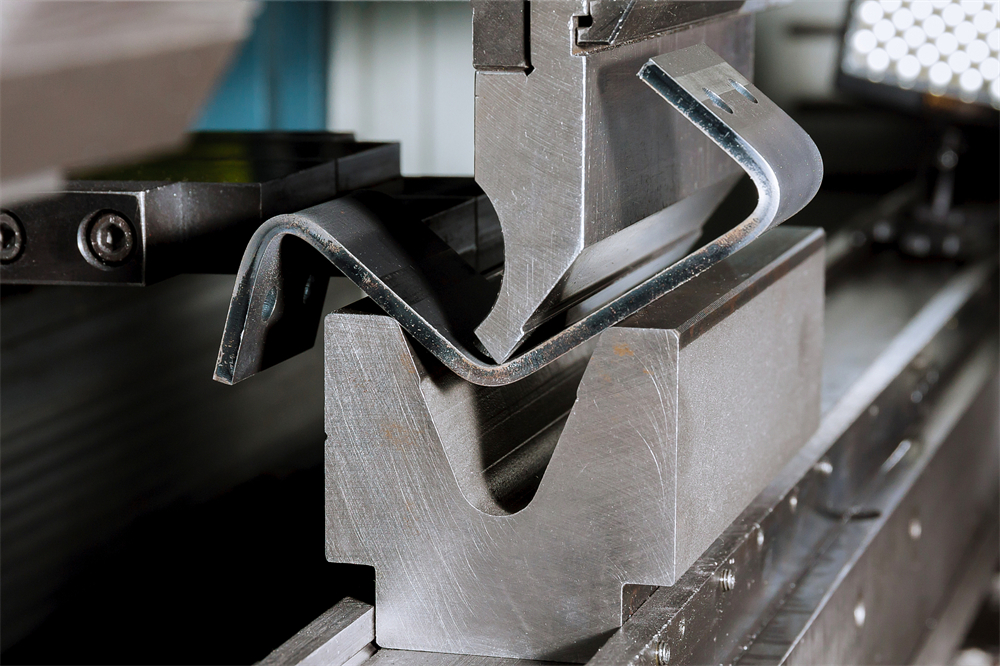
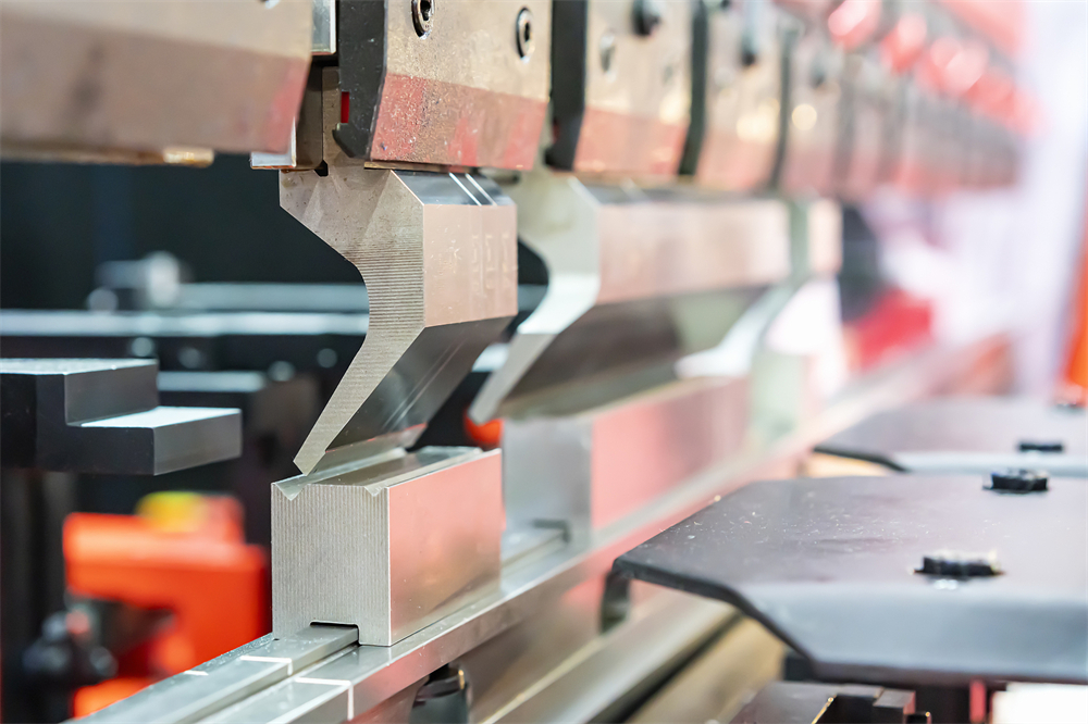
The primary hazard in press brake operation is the point of operation—the area where the upper punch meets the lower die to deform the metal. Without proper safety protocols, the risk of crush injuries or amputations is significant. To combat this, industrial metal fabrication facilities employ a multi-layered safety strategy. This includes physical barriers, presence-sensing devices, and rigorous operator training. Technical safety systems like laser guards (e.g., DSP or LazerSafe) and light curtains provide a virtual shield around the work zone, instantly halting the ram’s descent if an obstruction is detected. These systems are integrated directly into the machine’s PLC (Programmable Logic Controller), ensuring that safety is hard-wired into the machine’s logic.
Furthermore, the concept of ‘Safety by Design’ is central to HARSLE’s engineering philosophy. This involves optimizing the machine’s hydraulic response times and implementing redundant valve systems to prevent gravity-induced ram drops. In an industrial setting, the speed of production must never compromise the safety of the operator. Therefore, understanding the technical nuances of how these safety systems interact with the machine’s hydraulic and electrical circuits is essential for any safety officer or lead fabricator. This guide explores the critical parameters and methodologies required to maintain a zero-accident environment.
Core Parameters Influencing Operator Safety
When discussing Press Brake Operator Safety Industrial Metal Fabrication, several core technical parameters must be monitored and calibrated. The first is Tonnage Control. Operating a press brake beyond its rated capacity or using excessive force for a small workpiece can lead to tool breakage or machine failure, both of which pose projectile risks to the operator. Modern CNC systems allow for precise tonnage limiting, which should be set based on the material thickness, tensile strength, and bend length.
The second parameter is Ram Speed. Most industrial press brakes operate with a three-stage speed cycle: Rapid Approach, Pressing Speed, and Rapid Return. Safety regulations often dictate that the pressing speed (the speed at which the punch enters the die) must be limited—typically to 10mm/s or less—when safety devices are muted or when the operator is in close proximity. The ‘Mute Point’ is a critical parameter; it is the position in the stroke where the safety device (like a light curtain) is deactivated to allow the workpiece to pass through without triggering a stop. Setting this point too high exposes the operator to danger, while setting it too low can damage the material or the tools.
Another vital parameter is the Backgauge Safety Zone. While most focus is on the front of the machine, the backgauge moves with high speed and significant force. Operators must be aware of the ‘pinch points’ created between the backgauge fingers and the machine frame. Modern HARSLE machines often include safety sensors or software-defined ‘no-go’ zones for the backgauge to prevent collisions with the operator’s hands during part positioning. Finally, Stopping Time is perhaps the most critical safety parameter. This is the total time elapsed from the moment a safety device is triggered to the moment the ram comes to a complete halt. This value is used to calculate the minimum safety distance for guarding equipment.
Calculation Method for Safety Distance
To ensure Press Brake Operator Safety Industrial Metal Fabrication, the placement of safety devices like light curtains must be mathematically determined. The standard formula used globally, derived from EN ISO 13855, is used to calculate the Minimum Safety Distance (S). This distance ensures that an operator cannot reach the hazardous point-of-operation before the machine has reached a safe state.
The formula is: S = (K × T) + C
- S: The minimum safety distance in millimeters (mm) from the danger zone to the detection point of the safety device.
- K: The approach speed of the human body or parts of the body. For hand movements, the standard constant is typically 2000 mm/s if the distance is small, or 1600 mm/s for larger distances.
- T: The total response time of the entire system (in seconds). This includes the response time of the safety device (e.g., light curtain), the PLC processing time, and the mechanical stopping time of the hydraulic ram.
- C: The ‘Additional Distance’ or penetration factor. This accounts for how far a finger or hand can penetrate through the safety field before being detected, based on the resolution of the light curtain (e.g., 14mm for finger detection vs. 30mm for hand detection).
For example, if a HARSLE press brake has a total stopping time (T) of 0.1 seconds and uses a light curtain with a resolution that requires a C value of 80mm, the calculation would be: S = (2000 × 0.1) + 80 = 280mm. This means the light curtain must be mounted at least 280mm away from the center of the die. Failing to perform this calculation accurately can lead to a ‘false sense of security,’ where the operator is injured despite the safety device functioning correctly because it was placed too close to the hazard.
Safety Parameter Reference Table
The following table provides a reference for typical safety distances based on varying machine response times and safety device resolutions. Note: These are general industrial guidelines; always refer to your specific HARSLE machine manual for exact values.
| Machine Type | Total Stopping Time (ms) | Device Resolution (mm) | Constant K (mm/s) | Min. Safety Distance (mm) |
|---|---|---|---|---|
| High-Speed CNC | 80 | 14 (Finger) | 2000 | 160 |
| Standard Hydraulic | 120 | 14 (Finger) | 2000 | 240 |
| Heavy-Duty Large Scale | 200 | 30 (Hand) | 1600 | 448 |
| Retrofit Manual | 250 | 40 (Arm) | 1600 | 1250 (Barrier) |
It is crucial to conduct periodic ‘Stop Time Measurements’ using specialized equipment to ensure that the hydraulic valves and braking systems have not degraded over time. If the stopping time increases due to wear, the safety distance must be adjusted, or the machine must be serviced immediately to restore its original performance.
Common Engineering and Operational Mistakes
In the pursuit of productivity, several common mistakes often compromise Press Brake Operator Safety Industrial Metal Fabrication. One of the most frequent errors is Bypassing or ‘Cheating’ Safety Systems. Operators may tape over light curtain sensors or move laser guards out of alignment to facilitate faster part handling. This is a catastrophic failure of safety culture and often leads to severe accidents. Engineering controls should include tamper-evident mountings and software interlocks that prevent the machine from cycling if safety devices are not active.
Another common mistake is Improper Tooling Setup. Using tools that are too short for the workpiece or failing to properly secure the punch in the ram can lead to ‘tool fly-out.’ Furthermore, if the operator does not account for the ‘springback’ of the material, the part may whip upward unexpectedly during the release of the ram, striking the operator. This is particularly dangerous with large sheets of thin-gauge metal. Proper support systems, such as front support arms or CNC-controlled sheet followers, should be used to manage the material’s movement safely.
Inadequate Maintenance of Hydraulic Components is a silent killer in the fabrication shop. If the dual-redundant safety valves (monitored valves) become clogged with contaminated oil, they may fail to close properly, leading to ‘ram drift.’ Regular oil filtration and valve inspections are technical necessities for safety. Lastly, Poor Ergonomics often leads to operator fatigue, which is a leading cause of human error. If an operator is forced to stand in an awkward position or reach too far to cycle the machine, their reaction times slow down, and their likelihood of making a mistake increases. HARSLE recommends adjustable foot pedals and ergonomic workstations to keep operators alert and safe.
Selection Checklist for Safe Press Brake Acquisition
When selecting a new machine for your facility, use this checklist to ensure it meets the highest standards for Press Brake Operator Safety Industrial Metal Fabrication:
- Integrated Laser Guarding: Does the machine come with a recognized laser guarding system (e.g., DSP, LazerSafe, or Iris) that allows for close-proximity working without compromising safety?
- Dual-Monitored Hydraulic Valves: Are the main manifold valves redundant and monitored by the CNC system to prevent unintended ram movement?
- CNC Safety Logic: Does the controller have a dedicated safety PLC that manages emergency stops, light curtains, and interlocked side/rear gates?
- Tonnage Limiting: Can the machine automatically calculate and limit the required tonnage based on the programmed tool and material?
- Ergonomic Controls: Is the foot pedal shrouded to prevent accidental activation? Is the emergency stop button easily accessible from all operating positions?
- Tooling Clamping: Does the machine feature a secure clamping system (manual or hydraulic) with safety pins to prevent tools from falling during changeovers?
- CE/ANSI Compliance: Does the machine meet the specific safety standards required for your region (e.g., CE for Europe, ANSI B11.3 for North America)?
- Operator Training Program: Does the manufacturer provide comprehensive safety training and documentation for the specific model?
Frequently Asked Questions (FAQ)
1. What is the most effective safety device for a press brake?
For most industrial metal fabrication applications, a laser-based point-of-operation guard (like the LazerSafe system) is considered the most effective. Unlike light curtains, which are often muted during the stroke, laser guards move with the ram and protect the area just millimeters below the punch, allowing for high productivity and maximum safety.
2. How often should safety systems be tested?
Safety systems should be checked at the start of every shift. This includes a ‘block test’ for light curtains and a visual inspection of all emergency stops and interlocks. A professional stop-time measurement should be performed annually or whenever the hydraulic system undergoes major repairs.
3. Can I retrofit an old press brake with modern safety guards?
Yes, many older hydraulic press brakes can be retrofitted with light curtains or laser guards. However, this often requires upgrading the electrical control system to a safety-rated PLC to ensure the machine can interface correctly with the new devices. It is essential to consult with a specialist like HARSLE to ensure the retrofit meets current standards.
4. What PPE is required for press brake operators?
At a minimum, operators should wear ANSI-approved safety glasses, steel-toed boots, and cut-resistant gloves (when handling sharp sheet metal). Hearing protection may also be required depending on the shop’s ambient noise levels. Avoid loose clothing or jewelry that could get caught in moving parts.
5. What is ‘Muting’ in press brake safety?
Muting is the temporary, automatic suspension of a safety function during the non-hazardous part of the machine cycle. On a press brake, this usually happens once the punch is very close to the material (the mute point), allowing the bend to be completed without the workpiece itself triggering a safety stop.
6. Why is the backgauge considered a hazard?
The backgauge moves rapidly in multiple axes (X, R, Z1, Z2). If an operator reaches behind the tools to adjust a part while the backgauge is moving, there is a high risk of a pinch or crush injury between the gauge and the machine’s side frames or the workpiece itself.