Press Brake Safety System Faults: Troubleshooting Light Curtains, Foot Pedals, and Interlocks

Introduction to Press Brake Safety System Faults
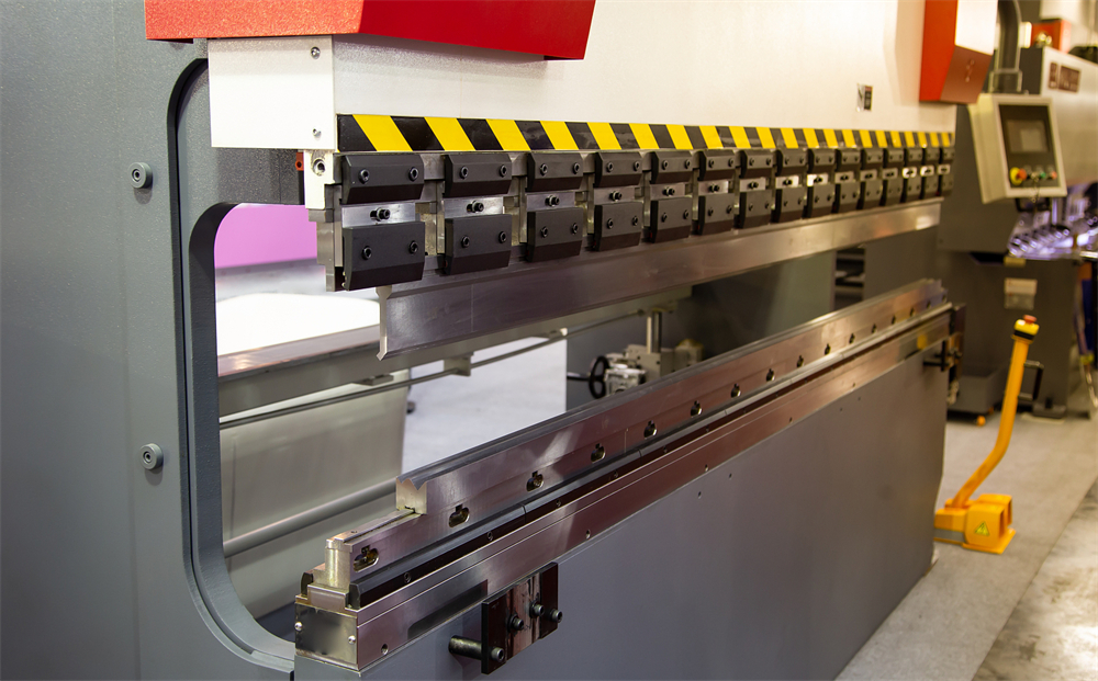
In the high-precision world of metal fabrication, the press brake stands as a cornerstone of production. However, the immense force required to bend heavy-gauge steel also presents significant risks to operators. Modern machinery, such as those manufactured by HARSLE, integrates sophisticated safety systems designed to prevent accidents. Despite their robustness, these systems can develop faults that halt production. Understanding Press Brake Safety System Faults: Troubleshooting Light Curtains, Foot Pedals, and Interlocks is essential for any maintenance team or shop manager looking to balance safety with operational efficiency.
Safety systems are not merely peripheral additions; they are deeply integrated into the machine’s logic controller. When a fault occurs in a light curtain, a foot pedal, or a physical interlock, the machine is designed to enter a ‘safe state,’ which usually means a complete lockout of the hydraulic system. While this prevents injury, it can lead to frustrating downtime if the root cause isn’t quickly identified. This guide provides a comprehensive technical deep-dive into diagnosing and resolving these common safety-related issues.
HARSLE machines utilize state-of-the-art safety components, but environmental factors, mechanical wear, and electrical interference can all trigger fault codes. By systematically approaching each component—from the optical sensors of light curtains to the mechanical switches in foot pedals—operators can minimize the duration of these interruptions. In the following sections, we will explore the technical nuances of these systems and provide actionable troubleshooting steps.
Key Considerations for Safety System Integrity
Before diving into specific component troubleshooting, it is vital to understand the regulatory and operational framework that governs press brake safety. Compliance with standards such as OSHA 1910.212 in the United States or the CE Machinery Directive in Europe is mandatory. These standards dictate that safety systems must be ‘fail-safe,’ meaning any failure within the safety circuit must result in the machine stopping safely rather than continuing to operate in a compromised state.
One of the primary considerations is the ‘Safety Category’ of the machine. Most modern press brakes are designed to Category 3 or 4, requiring redundancy. This means that if one relay fails, a second one is there to ensure the stop command is executed. When troubleshooting, you are often looking for a discrepancy between these redundant channels. If the PLC (Programmable Logic Controller) detects that Channel A is closed while Channel B is open, it will trigger a safety fault that cannot be reset until the discrepancy is resolved.
Operator training is another critical factor. Many ‘faults’ are actually the result of improper machine setup or the operator inadvertently blocking a sensor. For instance, if a workpiece is positioned such that it breaks the light curtain beam during the bending cycle without the proper ‘blanking’ or ‘muting’ parameters set in the CNC, the machine will stop. Distinguishing between a genuine hardware failure and a process-related interruption is the first step in effective troubleshooting.
Finally, environmental conditions in a fabrication shop can be harsh. Dust, oil mist, and vibration are the enemies of sensitive electronic safety components. Regular cleaning and vibration-damping mounts are not just maintenance tips; they are fundamental requirements for ensuring that safety systems do not provide ‘nuisance trips’ that tempt operators to bypass safety protocols—a dangerous practice that should never be tolerated.
Technical Details: Troubleshooting Light Curtains
Understanding Optical Alignment and Signal Strength
Light curtains are perhaps the most sensitive component of the safety circuit. They consist of a transmitter that sends infrared beams to a receiver. If any beam is broken, the safety relay opens. The most common fault in light curtains is misalignment. Over time, the vibrations from heavy bending operations can cause the mounting brackets to shift slightly. Even a few millimeters of movement can cause the receiver to lose the signal, triggering a fault.
Most modern light curtains feature LED indicators that show signal strength. A green light typically indicates a solid lock, while a flashing yellow or red light indicates a weak signal or total blockage. To troubleshoot, first clean the optical windows with a lint-free cloth and a non-abrasive cleaner. Accumulation of shop dust or oil can scatter the infrared beams. If cleaning doesn’t work, check the alignment using a laser alignment tool or by slowly adjusting the brackets while monitoring the signal strength LEDs on the receiver unit.
Muting and Blanking Faults
In complex bending operations, it is often necessary for the workpiece or the machine’s own tooling to pass through the light curtain’s field. This is handled through ‘muting’ (temporarily disabling the curtain during a specific part of the stroke) or ‘blanking’ (ignoring specific beams). Faults often occur when the CNC’s position sensors (encoders) do not match the expected state of the light curtain. For example, if the mute signal is triggered but the light curtain still detects an unexpected object, the system will lock out. Troubleshooting this requires checking the synchronization between the ram’s position and the safety PLC’s logic.
Electrical Interference and Cable Integrity
Because light curtains operate on low-voltage signals, they are susceptible to Electromagnetic Interference (EMI) from high-voltage components like the main motor or the hydraulic pump’s solenoid valves. Ensure that the safety cables are properly shielded and routed away from high-power lines. A common ‘ghost fault’—where the machine trips randomly—is often traced back to a frayed cable or a loose connector in the junction box. Inspect the entire length of the cable for nicks or sharp bends that could compromise the internal wiring.
Technical Details: Troubleshooting Foot Pedals
Mechanical Wear and Switch Redundancy
The foot pedal is the most frequently used interface on a press brake, making it highly susceptible to mechanical wear. Most safety foot pedals are ‘three-position’ switches: Released (Off), Pressed (Run), and Fully Pressed (Emergency Stop). If an operator panics and mashes the pedal down, the machine stops. A common fault occurs when the internal springs weaken or the mechanical linkage becomes clogged with debris, preventing the pedal from returning to the ‘Off’ position or causing it to skip the ‘Run’ position directly to ‘Emergency Stop’.
Inside the pedal, there are typically two or more microswitches providing redundant signals to the PLC. If one switch fails or becomes ‘sticky,’ the PLC will detect a timing discrepancy between the two channels and trigger a safety fault. Troubleshooting involves opening the pedal housing (after locking out power) and checking the switches for continuity using a multimeter. Ensure that both switches click and change state simultaneously when the pedal is depressed.
Cable Fatigue and Connector Corrosion
The cable connecting the foot pedal to the main cabinet is constantly moved, stepped on, and sometimes even run over by forklifts. This leads to internal wire breakage, particularly at the point where the cable enters the pedal housing. If the machine fails to start when the pedal is pressed, or if it cuts out intermittently, the cable is the primary suspect. Check for ‘soft spots’ in the cable that indicate internal breakage. Additionally, inspect the multi-pin connector at the machine base for bent pins or corrosion caused by coolant or moisture.
Technical Details: Troubleshooting Interlocks and Gates
Side and Rear Guard Interlocks
Press brakes are equipped with side and rear guards to prevent personnel from entering the hazardous area behind the ram. These guards are fitted with safety interlocks—either mechanical limit switches or non-contact magnetic/RFID sensors. A common fault occurs when these guards are not closed properly or become misaligned. If the machine displays a ‘Guard Open’ error despite the gates being closed, check the alignment of the sensor and its actuator. For magnetic sensors, even a small gap caused by a loose screw can prevent the circuit from closing.
Hydraulic Safety Valves and Monitoring
The safety system also monitors the state of the hydraulic valves. If the PLC sends a command to stop the ram, it monitors the feedback from the hydraulic valves to ensure they have actually shifted. If a valve is stuck due to contaminated oil or a burnt-out solenoid coil, the safety system will trigger a fault. This is a critical safety issue, as it indicates the machine may not be able to stop in an emergency. Troubleshooting involves checking the LED indicators on the valve solenoids and ensuring the hydraulic fluid is clean and at the correct temperature.
Selection Advice for Safety Systems
When purchasing a new HARSLE press brake or retrofitting an older machine, selecting the right safety system is paramount. Here are key factors to consider:
- Integration Level: Choose systems that are fully integrated into the CNC controller. This allows for easier ‘blanking’ and ‘muting’ setups directly from the screen, reducing the likelihood of operator-induced faults.
- Resolution of Light Curtains: For finger protection, a resolution of 14mm is standard. For hand protection, 30mm may suffice. Higher resolution provides better safety but requires more precise alignment.
- Environmental Rating: Ensure all safety components have an IP65 or higher rating to protect against dust and moisture common in metalworking environments.
- Brand Compatibility: Stick with reputable safety brands like Sick, Pilz, or Lazer Safe, which are commonly used by HARSLE. These brands offer extensive diagnostic tools that make troubleshooting much faster.
- Redundancy: Always opt for Category 4 safety systems for the highest level of protection and the most detailed fault diagnostics.
Investing in a high-quality safety system might have a higher upfront cost, but the reduction in ‘nuisance trips’ and the ease of troubleshooting will pay for itself in increased uptime and operator confidence. Always consult with the machine manufacturer before modifying any safety circuits, as unauthorized changes can void warranties and create legal liabilities.
Frequently Asked Questions (FAQ)
1. Why does my light curtain trip when there is nothing in the way?
This is usually caused by misalignment, dirty optical lenses, or electrical interference. Check that the transmitter and receiver are perfectly parallel and clean the glass with a soft cloth. Also, check for nearby high-voltage cables that might be causing EMI.
2. Can I bypass a faulty foot pedal to finish a job?
No. Bypassing any safety component is a violation of safety regulations and puts the operator at extreme risk of injury or death. If a foot pedal is faulty, it must be repaired or replaced before the machine is used.
3. What does a ‘Safety Relay Discrepancy’ error mean?
This means the two redundant channels of the safety circuit are not showing the same state. For example, one side of a dual-channel switch is closed while the other is open. This is often caused by a failing microswitch or a broken wire in one of the channels.
4. How often should I test the safety systems?
Safety systems should be tested at the beginning of every shift. This includes checking the light curtain function, the emergency stop buttons, and the foot pedal’s three-position functionality. Many CNCs have a built-in ‘Safety Check’ routine that must be completed before the machine will operate.
5. Why is my press brake stuck in ‘Slow Speed’ only?
This is often a safety feature. If the light curtains are not properly muted or if a safety zone is partially obstructed, the machine may limit itself to a ‘creep speed’ (usually 10mm/s or less) to prevent injury. Check your CNC settings and the state of the safety sensors.
6. How do I know if the fault is in the PLC or the hardware?
Most safety PLCs have diagnostic LEDs. If the input LED for a specific sensor is off when it should be on, the problem is likely the sensor or the wiring. If the input is on but the safety output remains off, the problem may be within the PLC logic or a secondary interlock condition not being met.
Conclusion
Maintaining the integrity of a press brake’s safety system is a continuous process that requires diligence, technical knowledge, and a commitment to workplace safety. Press Brake Safety System Faults: Troubleshooting Light Curtains, Foot Pedals, and Interlocks are challenges that every fabrication shop will face, but they don’t have to lead to prolonged downtime. By understanding the mechanical and electrical principles behind these components, maintenance teams can quickly diagnose issues and return the machine to service.
HARSLE continues to lead the industry by integrating the most reliable safety technologies into our machinery. However, the longevity and reliability of these systems ultimately depend on proper environment, regular maintenance, and correct operation. By following the troubleshooting steps outlined in this guide—cleaning sensors, checking cable integrity, and verifying mechanical alignments—you ensure that your press brake remains a productive and, most importantly, a safe asset for your business. Remember, a safe machine is a productive machine, and there is no shortcut to safety in the world of metal fabrication.