Press Brake Setup Guide: How to Achieve Accurate Bending Results


Technical Overview of Press Brake Precision
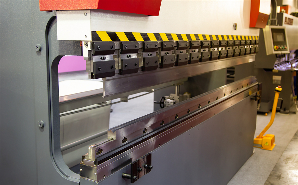
In the world of metal fabrication, the ability to produce consistent, high-quality bends is the hallmark of a professional operation. Achieving this level of precision starts long before the first piece of sheet metal is loaded into the machine. It begins with a comprehensive understanding of the Press Brake Setup : Achieve Accurate Bending Results. A press brake is a complex piece of industrial machinery designed to bend sheet and plate material, most commonly sheet metal. It forms predetermined bends by clamping the workpiece between a matching punch and die.
Modern press brakes, such as those manufactured by HARSLE, utilize advanced CNC (Computer Numerical Control) systems to manage the synchronization of hydraulic cylinders, the positioning of back gauges, and the compensation for frame deflection. However, even the most advanced CNC machine requires a skilled operator who understands the mechanical and metallurgical variables at play. The technical overview of a successful setup involves calibrating the machine’s axes, selecting the appropriate tooling for the material’s tensile strength, and ensuring the hydraulic system is operating at peak efficiency. Without a rigorous setup protocol, even minor deviations can lead to significant scrap rates and production delays.
The evolution from mechanical press brakes to high-precision hydraulic and electric models has significantly reduced the margin for error. Hydraulic press brakes use two synchronized cylinders on the side frames to move the upper beam. This movement must be perfectly parallel to ensure a uniform bend angle across the entire length of the workpiece. Furthermore, the frame of the machine itself undergoes slight deformation under high pressure, a phenomenon known as ‘deflection.’ Modern setups must account for this through crowning systems, which apply a counter-curve to the bed or beam to ensure the bend remains straight.
Ultimately, the goal of a technical setup is to create a repeatable process. This involves documenting every variable, from the specific die width used to the pressure settings on the CNC controller. By mastering the technical nuances of the press brake, fabricators can transition from simple 90-degree bends to complex multi-stage forming with confidence. This guide serves as a roadmap for operators and engineers to refine their setup procedures and maximize the output of their HARSLE machinery.
Core Parameters for Press Brake Setup
To Achieve Accurate Bending Results, one must meticulously manage several core parameters. The first and perhaps most critical is Tonnage. Tonnage is the amount of pressure the press brake must exert to perform a bend. If the tonnage is set too low, the bend will be incomplete; if it is set too high, you risk damaging the tooling, the machine, or the workpiece. Tonnage requirements are influenced by material thickness, material type (e.g., stainless steel vs. aluminum), and the width of the V-die opening.
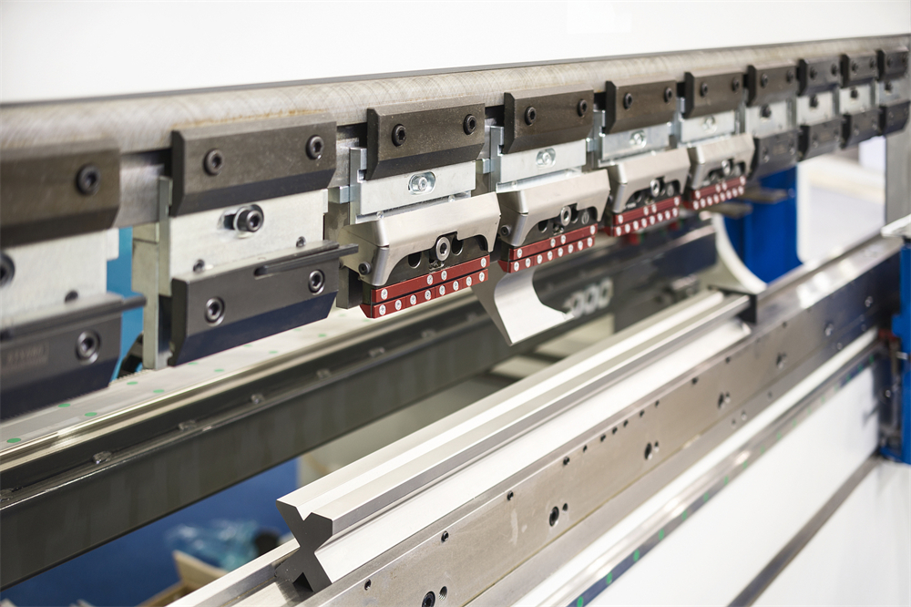
The second core parameter is the Tooling Selection. This includes the punch (the upper tool) and the die (the lower tool). The rule of thumb for air bending is that the V-die opening should be approximately 8 times the material thickness. However, for thicker materials or tighter radii, this ratio may change. The radius of the punch tip also plays a vital role in the final internal radius of the bend. Using a punch with a radius that is too small for the material can lead to ‘creasing’ or cracking, especially in high-tensile materials.
Thirdly, the Back Gauge Positioning (X, R, and Z axes) determines the accuracy of the bend’s flange length. The X-axis controls the depth of the gauge, the R-axis controls the height, and the Z-axis controls the lateral position of the gauge fingers. In a professional Press Brake Setup : Achieve Accurate Bending Results, these axes must be calibrated to within microns. Any misalignment here will result in parts that do not fit into subsequent assemblies, leading to costly rework.
Finally, the Stroke and Speed settings must be optimized. The stroke length determines how far the ram descends into the die. Modern CNC machines allow for ‘dwell time’ at the bottom of the stroke, which helps the material ‘set’ and reduces springback. Speed management is equally important; a fast approach speed saves time, but the actual bending speed must be controlled to prevent the material from ‘whipping’ up, which can be a safety hazard and cause inaccuracies in the bend angle.
Calculation Method for Precision Bending
Mathematical accuracy is the foundation of a successful press brake operation. To ensure the final part meets the design specifications, operators must calculate the Bend Allowance (BA) and Bend Deduction (BD). When metal is bent, the outer surface is stretched while the inner surface is compressed. Somewhere between these two surfaces lies the ‘Neutral Axis,’ which remains the same length. The K-factor is the ratio that represents the position of this neutral axis relative to the material thickness.
The formula for Bend Deduction is: BD = 2 * (R + T) * tan(A/2) – BA, where R is the inside radius, T is the material thickness, and A is the bend angle. Calculating this correctly ensures that the flat pattern of the sheet metal is cut to the exact size needed so that, after bending, the final dimensions are perfect. Most modern HARSLE CNC controllers have these formulas built-in, but the operator must input the correct material constants and K-factors to get accurate results.
Another essential calculation is the Tonnage Calculation. A common formula used in the industry is: P = (650 * T^2 * L) / V for mild steel, where P is pressure in tons, T is thickness, L is length of the bend in inches, and V is the V-die opening. For stainless steel, you typically increase the result by 50%. Understanding these calculations allows the operator to predict how the material will behave under pressure, preventing trial-and-error waste.
Lastly, one must calculate the Springback. Springback occurs because all metals have an elastic limit. When the pressure is released, the metal tries to return to its original shape. To compensate, the operator must ‘over-bend’ the part by a few degrees. The amount of springback depends on the material’s yield strength and the ratio of the bend radius to the material thickness. High-strength materials like T1 steel exhibit much more springback than soft aluminum, requiring precise adjustments in the CNC setup.
Press Brake Parameter Table (Mild Steel Reference)
The following table provides a general reference for setting up a press brake for mild steel (approx. 45,000 PSI yield strength). Note that these values are estimates and should be verified with your specific machine manual and material test reports.
| Material Thickness (mm) | Recommended V-Opening (mm) | Min. Flange Length (mm) | Inside Radius (mm) | Tonnage per Meter (T/m) |
|---|---|---|---|---|
| 1.0 | 8 | 5.5 | 1.3 | 7 |
| 1.5 | 12 | 8.5 | 2.0 | 11 |
| 2.0 | 16 | 11.5 | 2.6 | 15 |
| 3.0 | 24 | 17.0 | 4.0 | 22 |
| 4.0 | 32 | 22.0 | 5.3 | 30 |
| 6.0 | 50 | 35.0 | 8.0 | 45 |
| 8.0 | 63 | 45.0 | 10.5 | 70 |
| 10.0 | 80 | 55.0 | 13.0 | 95 |
When using this table, always remember that the V-opening choice directly impacts the tonnage. A narrower V-opening will result in a smaller inside radius but will significantly increase the tonnage required. Conversely, a wider V-opening reduces the tonnage but increases the minimum flange length required to bridge the die opening safely.
Common Engineering Mistakes in Press Brake Setup
Even experienced engineers can fall into traps that compromise the Press Brake Setup : Achieve Accurate Bending Results. One of the most common mistakes is ignoring the Grain Direction of the metal. Sheet metal is rolled at the mill, creating a longitudinal grain. Bending with the grain (parallel to it) increases the risk of cracking and results in more springback. Bending across the grain (perpendicular) is generally preferred for strength and consistency. If a part requires bends in multiple directions, the layout must be optimized to minimize grain-related failures.
Another frequent error is the use of Worn or Mismatched Tooling. Over time, the shoulders of a V-die can wear down, or the punch tip can become deformed. Using worn tools makes it impossible to achieve a consistent bend angle across the length of the part. Furthermore, mixing different brands of tooling can lead to height variations that the CNC controller cannot account for. It is essential to inspect tooling regularly and use precision-ground tools for high-accuracy jobs.
Failure to account for Crowning is a third major mistake. As mentioned earlier, the machine frame deflects under load. If the crowning system is not properly adjusted, the part will have a ‘canoe’ effect—where the angle in the middle of the bend is different from the angles at the ends. Operators often try to fix this by increasing the overall pressure, which only exacerbates the problem and can damage the machine. Proper setup involves calibrating the hydraulic or mechanical crowning system to match the specific tonnage of the job.
Finally, many operators neglect the importance of Machine Cleanliness and Lubrication. Dust, scale, and metal shavings can accumulate on the die or the back gauge fingers, leading to slight offsets in positioning. A piece of scale just 0.1mm thick trapped under the workpiece can change the bend angle by a full degree in precision air bending. Regular maintenance and a clean workspace are non-negotiable for those who want to Achieve Accurate Bending Results consistently.
Selection Checklist for Press Brake Setup
Before starting any production run, use this checklist to ensure your Press Brake Setup : Achieve Accurate Bending Results is optimized:
- Material Verification: Have you confirmed the material type, thickness, and tensile strength? Does it match the CNC program?
- Tooling Inspection: Are the punch and die in good condition? Is the V-opening appropriate (approx. 8x thickness)?
- Tonnage Limits: Is the calculated tonnage within the safe operating limits of the machine and the specific tools?
- Back Gauge Calibration: Are the gauge fingers clean and correctly positioned? Have they been homed recently?
- Crowning Adjustment: Is the crowning system set to compensate for the expected deflection at this tonnage?
- Safety Check: Are the light curtains or laser guards operational? Is the area clear of obstructions?
- First Article Inspection: Have you performed a test bend on a scrap piece of the same material?
- Springback Compensation: Have you adjusted the bend angle in the controller to account for the material’s elastic recovery?
- Grain Direction: Is the part oriented correctly relative to the material’s rolling direction?
- Lubrication: Are the sliding surfaces and the workpiece (if necessary) properly lubricated to prevent galling?
Frequently Asked Questions (FAQ)
1. Why is my bend angle inconsistent across the length of the part?
This is usually caused by machine deflection. When the press brake applies pressure, the center of the beam and bed bow away from each other. To fix this, you need to adjust your machine’s crowning system (either hydraulic or mechanical) to provide a counter-bow. Additionally, check that your tooling is not worn in the center.
2. How do I choose the right V-die opening?
The standard choice for air bending mild steel is 8 times the material thickness (8T). For thinner materials (under 3mm), you might use 6T to get a tighter radius. For very thick materials (over 12mm), 10T or 12T is often used to keep tonnage requirements within the machine’s capacity. Using a larger V-opening reduces tonnage but increases the minimum flange length.
3. What is the difference between Air Bending and Bottoming?
In air bending, the workpiece only touches the two shoulders of the die and the tip of the punch. The angle is determined by how deep the punch descends. In bottoming, the punch presses the material fully into the die, conforming to the die’s angle. Air bending is more versatile and requires less tonnage, while bottoming provides higher accuracy but is limited to specific angles and requires much higher pressure.
4. How does material temperature affect bending accuracy?
Extreme temperature changes can affect the viscosity of the hydraulic oil, which may slightly alter the ram’s positioning in older machines. More importantly, very cold metal can be more brittle and prone to cracking, while very hot metal may have slightly different tensile properties. For maximum precision, it is best to operate in a climate-controlled environment.
5. Can I bend stainless steel using the same settings as mild steel?
No. Stainless steel is much harder and has higher tensile strength. It typically requires about 50% more tonnage than mild steel of the same thickness. It also has more springback, meaning you will need to over-bend the part further to achieve the desired final angle. Always use hardened tooling when working with stainless steel to prevent premature wear.
6. How often should I calibrate my back gauge?
For high-precision shops, a daily homing procedure is standard. A full calibration check against physical blocks or calipers should be performed weekly or whenever the machine has been moved or subjected to a hard stop/collision. Accurate back gauges are essential to Achieve Accurate Bending Results.