Comprehensive Guide: How to Inspect Hydraulic Press Valves for Smooth Operation

Introduction to Hydraulic Press Valve Maintenance
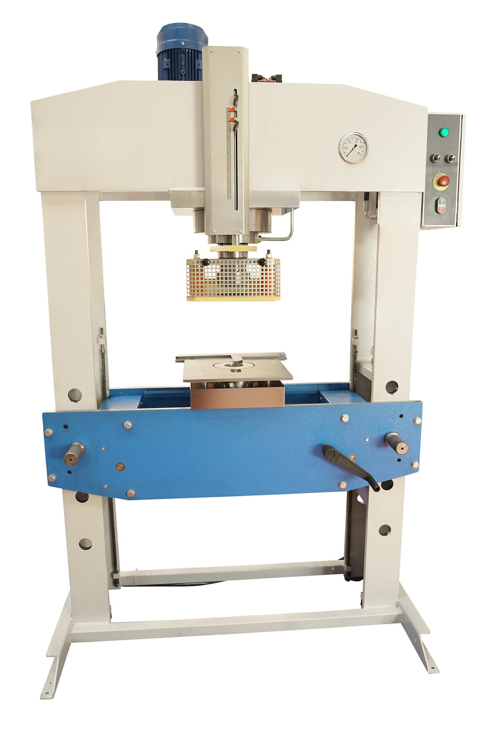
In the world of heavy industrial manufacturing, the hydraulic press stands as a cornerstone of productivity. Whether it is used for deep drawing, stamping, forging, or molding, the efficiency of a hydraulic press is dictated by the precision of its fluid power system. At the heart of this system lie the valves. Understanding how to inspect hydraulic press valves for smooth operation is not merely a maintenance task; it is a critical operational requirement that ensures safety, precision, and longevity of the equipment. HARSLE, a leader in metal fabrication machinery, emphasizes that a well-maintained valve system can reduce energy consumption by up to 20% and prevent catastrophic mechanical failures.
Hydraulic valves are responsible for directing the flow of high-pressure oil, regulating pressure levels, and controlling the speed of the ram. When these components begin to fail or operate inefficiently, the entire production line suffers. From erratic ram movements to excessive heat generation, the symptoms of valve wear are often subtle before they become destructive. This comprehensive guide will walk you through the intricate processes of inspecting, maintaining, and troubleshooting hydraulic press valves to ensure your workshop remains productive and safe.
The Critical Importance of Valve Maintenance
The primary reason to inspect hydraulic press valves for smooth operation is the prevention of unplanned downtime. In a high-volume production environment, a single hour of downtime can cost thousands of dollars in lost revenue. Valves are precision-engineered components with extremely tight tolerances. Even microscopic contaminants in the hydraulic fluid can cause scoring on valve spools, leading to internal leakage and loss of pressure control.
Safety is another paramount concern. A sticking directional control valve can cause the press ram to drop unexpectedly or fail to stop during an emergency cycle. By implementing a rigorous inspection routine, operators can identify potential hazards before they manifest as accidents. Furthermore, consistent maintenance preserves the accuracy of the press. For precision metal forming, even a slight fluctuation in pressure—caused by a faulty relief valve—can result in rejected parts and wasted material. Finally, regular inspections extend the overall lifespan of the hydraulic pump. When valves operate smoothly, the pump does not have to work overtime to compensate for pressure drops or flow restrictions, thereby reducing wear on the most expensive component of the hydraulic system.
Daily Inspection Protocols for Operators
Daily inspections are the first line of defense against machinery failure. Before the start of every shift, operators should perform a visual and auditory sweep of the hydraulic manifold and valve assemblies. Start by checking for external leaks. Even a small damp spot around a valve flange or solenoid connection can indicate a failing seal or a loose mounting bolt. High-pressure leaks are not only messy but can also be dangerous, posing a risk of fluid injection injuries.
Next, listen to the machine as it cycles. A healthy hydraulic system has a consistent, rhythmic hum. If you hear high-pitched whining, chattering, or banging (water hammer), it often points to issues within the valves. Chattering is frequently a sign of a relief valve that is rapidly opening and closing due to pressure instability or a broken internal spring. Additionally, check the temperature of the valve bodies. While hydraulic systems run warm, a valve that is significantly hotter than the surrounding components may be experiencing internal bypass, where high-pressure oil is forced through a small gap, generating intense localized heat.
In-Depth Hydraulic Component Checks
To truly inspect hydraulic press valves for smooth operation, one must look beyond the surface. The hydraulic system consists of several types of valves, each requiring specific inspection techniques. The pressure relief valve is perhaps the most critical. It acts as the safety fuse of the system. During inspection, verify that the relief valve is set to the manufacturer’s recommended PSI. Use a calibrated pressure gauge to ensure the valve opens at the correct threshold and, more importantly, reseats fully once the pressure drops. A relief valve that “weeps” below its set point will cause the system to lose power and overheat.
Directional control valves (DCVs) should be checked for shifting speed and completeness. If the ram takes longer to respond to a command than usual, the DCV spool may be dragging due to varnish buildup or physical wear. For proportional valves, which handle complex speed and position ramping, inspection involves checking the electronic feedback loop. These valves are highly sensitive to oil cleanliness; therefore, the inspection of the associated sub-plate filters is mandatory. Check valves, which allow flow in only one direction, should be tested for backflow leakage. A failing check valve can cause the ram to drift downward when the press is stopped in mid-stroke, a major safety violation in any shop.
Electrical and Solenoid System Verification
Modern HARSLE hydraulic presses rely heavily on electrical signals to actuate valves. Therefore, inspecting the electrical side is just as important as the hydraulic side. Solenoids are the electromagnetic coils that move the valve spools. Over time, these coils can degrade due to heat or voltage fluctuations. Inspect the solenoid connectors (often DIN connectors) for signs of corrosion or loose wiring. A flickering signal can cause the valve to “stutter,” leading to jerky machine movements.
Use a multimeter to check the resistance of the solenoid coils. If the resistance is significantly higher or lower than the manufacturer’s specification, the coil is likely failing and should be replaced. Additionally, check the PLC (Programmable Logic Controller) outputs. Sometimes, what appears to be a mechanical valve failure is actually a faulty relay or a corrupted software parameter in the control cabinet. Ensure that all proximity sensors and limit switches that interface with the valves are clean and properly aligned, as they provide the “permissives” required for the valves to shift.
Mechanical Integrity and Physical Wear
The mechanical structure of the valve assembly must be rigid. Vibration is a common enemy of hydraulic systems. During your monthly deep-dive inspection, check the torque on all valve mounting bolts. Loose valves can lead to O-ring failure at the sub-plate interface. Speaking of O-rings, any time a valve is removed for inspection, the seals should be replaced as a matter of course. Hardened or flattened seals are a primary cause of external leakage.
Internal mechanical wear is harder to detect but can be assessed through “drift tests.” By holding the press ram under pressure and monitoring its position over time, you can determine if internal leakage is occurring across the valve spools. If the spool-to-bore clearance exceeds the design limits (often measured in microns), the valve will no longer be able to hold pressure effectively. In such cases, the valve must be sent for professional refurbishment or replaced. Also, inspect the manual override pins on the solenoids. These should move freely; if they are stuck, it indicates that the internal spool is jammed by debris or is physically distorted.
The Lubrication and Fluid Quality Plan
You cannot inspect hydraulic press valves for smooth operation without inspecting the fluid that flows through them. Hydraulic oil is not just a medium for power; it is a lubricant and a coolant. The number one cause of valve failure is contaminated oil. Implement a fluid analysis program where oil samples are sent to a lab quarterly. Look for the “ISO Cleanliness Code.” For high-performance valves, a code of 16/14/11 or better is often required.
Check the oil filters regularly. If the bypass indicator on the filter housing is tripped, it means the oil is bypassing the filter and sending contaminants directly into the valves. Furthermore, monitor the oil viscosity. If the oil is too thin (due to overheating or shearing), it won’t provide the necessary film strength to protect the valve spools. If it is too thick (due to cold temperatures or oxidation), the valves will be sluggish. Ensure the hydraulic reservoir is filled to the correct level and that the breathers are clean to prevent airborne dust from entering the system and acting as an abrasive inside the valve bodies.
Troubleshooting Common Valve Signals
When the inspection reveals an issue, troubleshooting must be systematic. If the press is experiencing “spongy” operation, this is often a sign of air trapped in the valve manifold. Bleeding the system and checking the suction line of the pump for leaks is the standard fix. If the press fails to build pressure, the primary suspect is the main relief valve. It may be stuck open by a piece of metal shaving or a broken spring. Cleaning the valve orifice often resolves this without needing a full replacement.
Another common signal is “hunting,” where the press ram oscillates slightly when it should be stationary. This usually points to a problem with a proportional valve’s PID tuning or a worn-out centering spring inside a directional valve. If the valves are exceptionally noisy, check for cavitation. Cavitation occurs when air bubbles form and collapse violently within the valve, which can pit the metal surfaces and lead to rapid failure. This is often caused by a clogged suction strainer or a restricted inlet line. By recognizing these signals early, you can perform targeted maintenance rather than guessing and replacing expensive parts unnecessarily.
Comprehensive Maintenance Schedule Table
To maintain a high standard of operation, follow this structured maintenance schedule designed for HARSLE hydraulic presses and similar industrial machinery.
| Frequency | Component | Action Required | Goal |
|---|---|---|---|
| Daily | Valve Manifold | Visual check for leaks and external debris. | Prevent fluid loss and fire hazards. |
| Daily | Solenoids | Listen for unusual clicking or humming. | Identify electrical instability. |
| Weekly | Pressure Settings | Verify system pressure against the gauge. | Ensure consistent tonnage. |
| Monthly | Mounting Bolts | Check torque on all valve and sub-plate bolts. | Reduce vibration-related wear. |
| Monthly | Filters | Inspect bypass indicators and replace if needed. | Maintain oil cleanliness. |
| Quarterly | Hydraulic Oil | Perform lab analysis for particle count and water. | Extend valve spool life. |
| Bi-Annually | Electrical Wiring | Inspect insulation and tighten terminal screws. | Prevent intermittent signal loss. |
| Annually | Full System Flush | Drain, clean reservoir, and replace all fluid. | Remove accumulated sludge and varnish. |
Advanced Inspection Techniques: Thermal Imaging and Ultrasonics
For large-scale operations, traditional inspection might not be enough. Advanced techniques like thermal imaging allow maintenance teams to see heat patterns in the valve manifold without stopping the machine. A “hot spot” on a specific valve section clearly indicates internal bypass or a failing solenoid coil. This non-destructive testing (NDT) method is highly effective for predictive maintenance.
Ultrasonic leak detection is another powerful tool. Even when a valve is closed, internal leakage creates a specific high-frequency sound signature. Ultrasonic sensors can pick up these sounds, allowing technicians to pinpoint which valve in a complex manifold is leaking internally. By adopting these Industry 4.0 technologies, HARSLE users can move from reactive maintenance to a proactive strategy, ensuring that the instruction on how to inspect hydraulic press valves for smooth operation is backed by data-driven insights.
Frequently Asked Questions (FAQ)
1. How often should I replace the seals in my hydraulic valves?
Seals should generally be inspected every 6 months and replaced every 12 to 24 months, depending on the duty cycle and operating temperature. If the press operates in a high-heat environment, seals may harden and fail sooner. Always use high-quality Viton or Nitrile seals recommended by HARSLE.
2. Why does my hydraulic press ram drift down when the valve is in neutral?
Ram drift is usually caused by internal leakage in the directional control valve or a faulty pilot-operated check valve. It can also be caused by worn piston seals in the hydraulic cylinder itself. Inspect the valves first, as they are the most common culprits for pressure loss in the holding circuit.
3. Can I clean a hydraulic valve myself, or should I buy a new one?
Many valve issues are caused by simple contamination. If you have a clean, dust-free environment, you can disassemble the valve, clean the parts with a lint-free cloth and fresh hydraulic oil, and reassemble it. However, if the spool or bore is physically scored or scratched, the valve will likely need professional honing or replacement to restore its seal.
4. What is the best way to prevent varnish buildup in valves?
Varnish is a byproduct of oil oxidation, usually caused by high operating temperatures. To prevent it, keep your oil temperature below 60°C (140°F), use high-quality anti-wear hydraulic oil, and consider using an off-line “kidney loop” filtration system with a varnish-removal element.
5. How do I know if my relief valve is set too high?
If the relief valve is set too high, you will notice the pump straining, excessive heat in the oil, and potentially leaking hoses or seals. The system pressure should never exceed the maximum rated pressure of the weakest component in the circuit. Always refer to your HARSLE manual for the specific pressure settings for your model.
6. What are the signs of a failing solenoid?
Signs include the valve failing to shift, the coil becoming extremely hot to the touch, a burnt smell, or the valve shifting intermittently. You can test the solenoid by swapping it with a known good coil of the same specification to see if the problem follows the coil.
Conclusion
Learning how to inspect hydraulic press valves for smooth operation is an investment in the future of your manufacturing capabilities. By combining daily visual checks with technical electrical testing and rigorous fluid management, you can ensure that your HARSLE hydraulic press operates with the precision and power it was designed for. Remember that the hydraulic system is a closed loop; what affects one component eventually affects them all. Keep your valves clean, your oil cool, and your inspections consistent, and your machinery will provide decades of reliable service in the demanding world of metal fabrication.


