Best Practices for Press Brake Die and Punch Setup: A Comprehensive Technical Guide


Technical Overview of Press Brake Tooling Systems
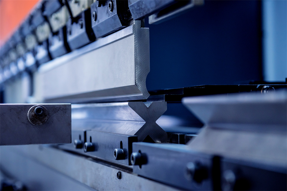
In the realm of precision metal fabrication, the setup of the press brake die and punch is the single most critical factor determining the quality, accuracy, and repeatability of the finished component. A press brake operates by using a punch (the upper tool) to force sheet metal into a die (the lower tool), creating a specific bend angle. While the concept is straightforward, the physics involved—including material displacement, tensile stress, and springback—require a sophisticated understanding of tooling dynamics. Implementing Best Practices Press Brake Die Punch Setup ensures that the machine operates within its design limits while minimizing wear and tear on expensive tooling components.
Modern CNC press brakes, such as those manufactured by HARSLE, utilize advanced hydraulic systems and electronic feedback loops to control the ram’s position. However, even the most advanced machine cannot compensate for a poorly configured tool set. The interaction between the punch radius and the die opening (V-width) dictates the inside bend radius of the part. Understanding the difference between air bending, bottoming, and coining is essential. Air bending is the most common method today, where the punch does not press the material into the bottom of the die, allowing for a wide range of angles with a single tool set. Bottoming and coining, while providing higher precision, require significantly more tonnage and specific tool geometries.
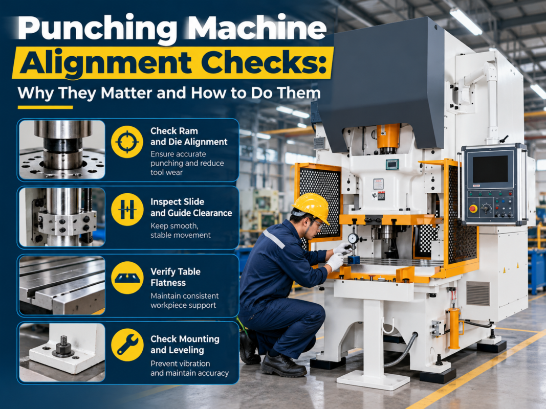
The technical integrity of the setup also depends on the alignment of the tools. Misalignment can lead to uneven bends, excessive side-loading on the ram, and even catastrophic tool failure. For high-tonnage applications, the structural integrity of the tool holders and the bed must be verified. This technical overview serves as the foundation for understanding why specific parameters and calculation methods are non-negotiable in a professional fabrication environment.
Core Parameters for Effective Tooling Setup
When establishing the Best Practices Press Brake Die Punch Setup, several core parameters must be evaluated before the first bend is attempted. The first parameter is the V-opening width. As a general rule of thumb, the V-opening should be approximately 8 times the material thickness (8T) for materials up to 1/2 inch thick. For thinner materials, this ratio might drop to 6T, while for thicker plates, it may increase to 10T or 12T to reduce the required tonnage and prevent cracking.
The punch radius is the second critical parameter. Ideally, the punch radius should be as close as possible to the natural inside bend radius of the material. If the punch radius is too small, it can act as a knife, piercing the material or creating a “sharp bend” that weakens the structural integrity of the part. Conversely, a punch radius that is too large may result in inconsistent bend angles due to increased springback. In air bending, the inside radius is typically about 15% to 17% of the V-opening width, regardless of the punch radius, provided the punch radius is smaller than that value.
Another vital parameter is the die angle. For air bending, the die angle is usually 85 or 88 degrees to allow for springback compensation. If you are bending a 90-degree angle, the punch must over-bend the material slightly. The machine’s stroke depth, controlled by the CNC, determines the final angle. Additionally, the load capacity of the tools themselves must be checked. Every punch and die has a maximum tonnage per foot or meter rating. Exceeding this limit can cause the tool to explode, posing a severe safety risk to the operator and damaging the machine bed.
Calculation Method for Tonnage and Bend Allowance
Accurate calculations are the backbone of any successful press brake setup. The most important calculation is the required tonnage. The formula for estimating the tonnage (P) required for air bending mild steel is: P = (k * L * S^2) / V. In this formula, P is the tonnage in tons, k is a material constant (usually 1.45 for mild steel), L is the length of the bend in inches, S is the material thickness in inches, and V is the V-opening width in inches. If you are bending stainless steel, you must multiply the result by approximately 1.5 due to the higher tensile strength of the material.
Beyond tonnage, calculating the bend allowance (BA) and bend deduction (BD) is necessary for flat pattern development. The bend allowance is the length of the arc through the neutral axis of the material. The formula is: BA = A * (π/180) * (R + K * S), where A is the bend angle, R is the inside bend radius, S is the thickness, and K is the K-factor (typically 0.3 to 0.5 depending on the material and bending method). Accurate BA calculations ensure that the final dimensions of the bent part match the engineering drawings.
Finally, operators must calculate the “minimum flange length.” Every V-die has a minimum distance required for the material to bridge the opening securely. If the flange is too short, the material will slip into the die, resulting in a failed bend and potential damage to the die edges. This is usually calculated as Min Flange = (V / 2) * 1.414 for a 90-degree bend. Incorporating these calculations into the setup phase is a hallmark of Best Practices Press Brake Die Punch Setup.
Parameter Table: Material Thickness vs. V-Opening
The following table provides a reference guide for selecting the appropriate V-opening and estimating the tonnage required per foot for mild steel (tensile strength approx. 450 MPa).
| Material Thickness (mm) | Recommended V-Opening (mm) | Inside Radius (mm) | Min. Flange Length (mm) | Tonnage per Meter (T/m) |
|---|---|---|---|---|
| 1.0 | 8 | 1.3 | 5.5 | 7 |
| 1.5 | 12 | 2.0 | 8.5 | 11 |
| 2.0 | 16 | 2.6 | 11.5 | 15 |
| 3.0 | 24 | 4.0 | 17.0 | 23 |
| 4.0 | 32 | 5.3 | 22.5 | 30 |
| 6.0 | 50 | 8.0 | 35.0 | 45 |
| 8.0 | 63 | 10.5 | 45.0 | 65 |
| 10.0 | 80 | 13.5 | 57.0 | 80 |
Note: These values are for air bending mild steel. For stainless steel, increase tonnage by 50%. For aluminum, decrease tonnage by 30-50% depending on the alloy.
Common Engineering Mistakes in Tooling Setup
One of the most frequent mistakes in press brake setup is the failure to properly seat the punch in the ram. If the punch is not perfectly centered and clamped, it can shift under pressure, leading to inaccurate bend angles and potential damage to the clamping system. Operators should always perform a “zero-ing” or “homing” procedure after installing new tools to ensure the CNC system recognizes the exact position of the punch tip relative to the die.
Another common error is ignoring the “tonnage limit” of the tooling. Many operators assume that if the machine is rated for 100 tons, they can use any tool to exert that force. However, a narrow punch or a small V-die may only be rated for 20 tons per foot. Concentrating 100 tons of force onto a tool rated for 20 tons will lead to deformation or fracture. This is especially dangerous when using short pieces of tooling to perform high-pressure bends, a practice known as “point loading.”
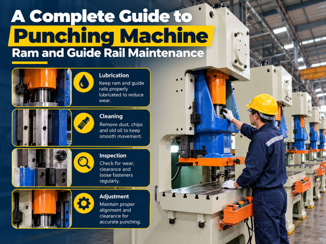
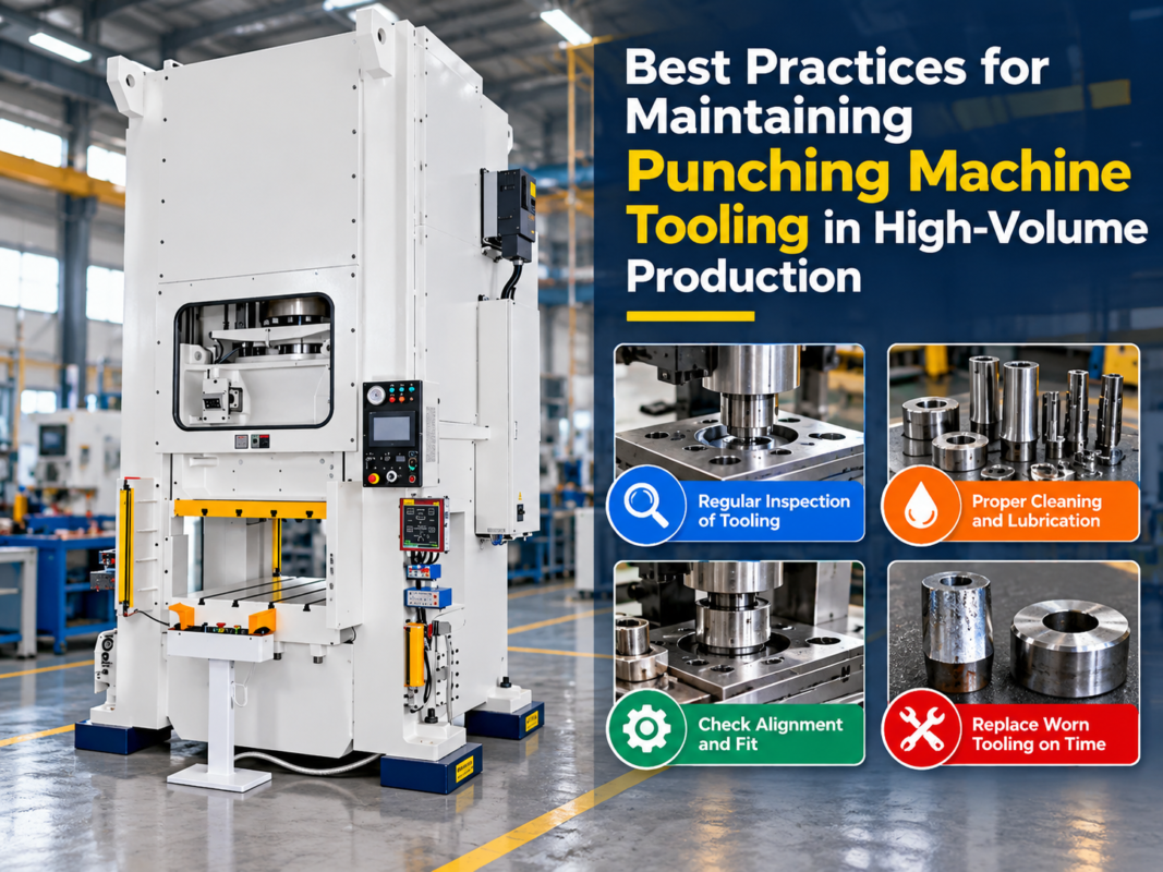
Neglecting tool maintenance is a third major pitfall. Over time, the shoulders of the V-die and the tip of the punch wear down. This wear changes the effective V-opening and the punch radius, leading to inconsistent results. Furthermore, debris such as mill scale or metal dust can accumulate in the die. If not cleaned, this debris can be pressed into the workpiece, causing surface imperfections, or it can sit under the die, causing it to tilt slightly. Regular inspection and cleaning are essential components of Best Practices Press Brake Die Punch Setup.
Selection Checklist for Press Brake Tooling
Choosing the right tools is as important as the setup itself. Use this checklist to ensure your selection aligns with industrial standards:
- Material Compatibility: Does the tool material (e.g., 42CrMo) match the hardness and tensile strength of the workpiece?
- Tonnage Rating: Is the maximum tonnage of the punch and die higher than the calculated required tonnage for the job?
- Bend Radius Requirements: Does the punch radius meet the minimum requirements to avoid material cracking?
- V-Opening Selection: Is the V-opening approximately 8x the material thickness for optimal results?
- Tool Height: Are the punch and die heights compatible with the machine’s open height and stroke length?
- Sectionalized Tooling: If the bend is complex, do you have the necessary sectionalized pieces to avoid interference?
- Surface Finish: For aesthetic parts, are you using nylon inserts or polished dies to prevent marking?
Maintenance and Safety Protocols
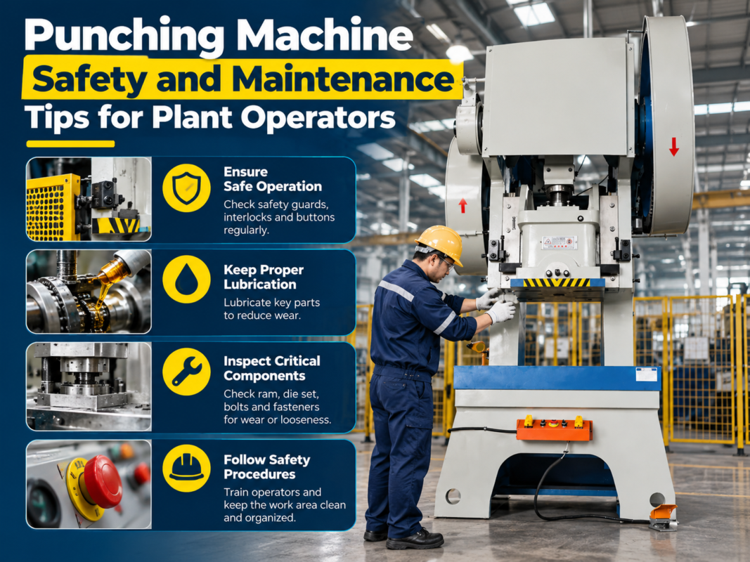
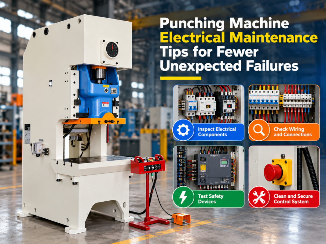
Safety is paramount when dealing with the high forces of a press brake. Before every setup, the operator must inspect the tools for visible cracks, chips, or signs of fatigue. A tool that fails under pressure can eject metal shards at high velocity. Always use the machine’s safety features, such as light curtains or laser guards, and ensure they are calibrated to the specific height of the tools being used. During the setup of Best Practices Press Brake Die Punch Setup, never place hands between the tools while the pump is running or the ram is in motion.
Maintenance should be scheduled and documented. This includes lubricating the tangs of the tools and the clamping surfaces to prevent galling. For CNC machines, the backgauge fingers should also be checked for alignment and wear, as they determine the flange dimensions. If using a hydraulic clamping system, check for leaks and ensure the pressure is within the manufacturer’s specified range. Proper storage is also a form of maintenance; tools should be stored in a dry environment on wooden or plastic racks to prevent corrosion and accidental damage to the precision-ground surfaces.
Frequently Asked Questions
What is the difference between air bending and bottoming?
Air bending involves the punch pressing the material into the die without touching the bottom of the V-opening. The angle is determined by the depth of the stroke. Bottoming involves pressing the material against the bottom of the die, which requires more force but offers higher precision and less springback.
How do I choose the right V-opening for stainless steel?
For stainless steel, it is often recommended to use a slightly larger V-opening (10T to 12T) than you would for mild steel. This reduces the tonnage required and helps manage the significant springback characteristic of stainless alloys.
Why is my bend angle inconsistent across the length of the part?
This is often caused by “machine deflection.” The center of the ram and bed may bow slightly under pressure. To fix this, many HARSLE press brakes include a “crowning” system that compensates for this deflection by slightly raising the center of the bed.
Can I use a punch with a smaller radius than the material thickness?
It is possible, but not recommended for most applications. Using a punch radius smaller than the material thickness can cause “sharp bending,” which creates a crease in the material and can lead to cracking or structural failure of the part.
How often should I replace my press brake tooling?
Tooling should be replaced when it shows signs of wear that affect the accuracy of the parts. This depends on the material being bent (abrasive materials like hot-rolled steel wear tools faster) and the frequency of use. Regular measurement of the punch tip and die shoulders will indicate when replacement is necessary.
What is the ‘8-times rule’ in press brake setup?
The 8-times rule is a standard guideline suggesting that the V-opening of the die should be eight times the thickness of the material being bent. This provides a balance between manageable tonnage and a clean, consistent bend radius.