Press Brake Back Gauge Adjustment Guide for Repeatable Bending Precision


Technical Overview: The Role of the Back Gauge in Modern Bending
In the realm of precision metal fabrication, the press brake back gauge is the unsung hero of the production floor. While the ram and the tooling provide the force and the shape, the back gauge determines the accuracy and repeatability of every single bend. Press brake back gauge adjustment for repeatable bending precision is not merely a matter of setting a distance; it is a complex interplay of mechanical alignment, electronic control, and metallurgical understanding. A back gauge functions as a high-precision positioning system that holds the workpiece in the exact location required for the punch to meet the die at the correct point on the sheet metal.
Modern CNC back gauges have evolved from simple manual stops to sophisticated multi-axis robotic systems. These systems utilize high-speed servo motors, precision ball screws, and linear guides to move fingers along various axes (X, R, Z). The precision of these movements is typically measured in microns, as even a deviation of 0.1mm can result in a rejected part, especially in industries like aerospace or medical device manufacturing. HARSLE machines integrate advanced CNC controllers that synchronize these movements with the ram’s stroke, ensuring that the back gauge retracts just before the bend is completed to prevent interference or ‘kick-back’ damage.
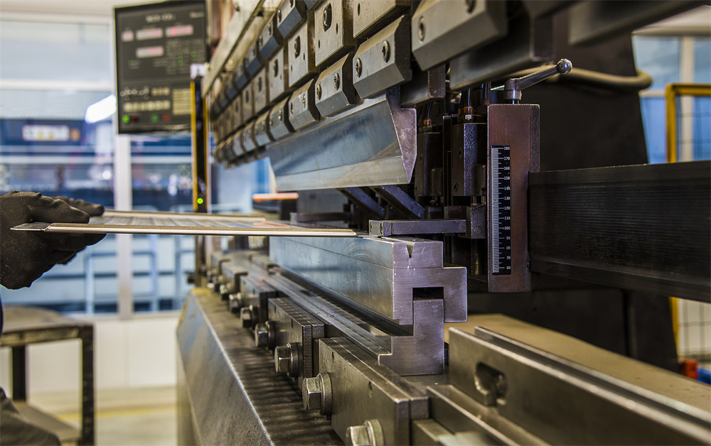
Repeatability is the cornerstone of mass production. If a back gauge cannot return to the exact same position within a tolerance of +/- 0.01mm, the cumulative error across a batch of 500 parts will lead to significant assembly issues. Achieving this level of precision requires a deep understanding of the machine’s mechanical limits and the software’s compensation algorithms. Factors such as the rigidity of the back gauge frame, the quality of the linear bearings, and the resolution of the encoders all play a vital role in the final output quality.
Core Parameters of Back Gauge Positioning
To master press brake back gauge adjustment for repeatable bending precision, one must first understand the various axes involved. The standard configuration for a high-end CNC press brake includes at least three primary axes, though advanced models can feature up to six or more. The X-axis is the most critical, representing the forward and backward movement of the gauge fingers. This axis determines the flange length of the bend. Precision in the X-axis is maintained through the use of pre-loaded ball screws that eliminate backlash, ensuring that the gauge always knows its absolute position relative to the center of the die.
The R-axis controls the vertical movement of the back gauge fingers. This is essential when working with dies of different heights or when performing bends that require the sheet to be supported at a specific elevation. If the R-axis is not correctly adjusted, the sheet metal may sit at an angle, leading to a ‘tapered’ bend where one end of the flange is longer than the other. Furthermore, the Z-axis (Z1 and Z2) allows the fingers to move left and right along the length of the machine. This is crucial for supporting long workpieces or for positioning multiple fingers to handle complex, asymmetrical shapes.
Beyond the basic X, R, and Z axes, some advanced HARSLE press brakes feature X1/X2 and R1/R2 axes. This allows for independent movement of each gauge finger, enabling the operator to perform tapered bends or to support parts that do not have a straight edge to gauge against. Understanding how to program these independent movements is key to handling complex geometries without the need for custom, expensive jigging. Each axis must be calibrated regularly to ensure that the software’s digital readout matches the physical reality of the machine’s geometry.
Calculation Method for Precision Positioning
Calculating the correct back gauge position involves more than just measuring the desired flange length. The operator must account for the Bend Allowance (BA) and the Bend Deduction (BD). When metal is bent, the outer surface stretches and the inner surface compresses. The ‘neutral axis’ is the theoretical line where no deformation occurs. The back gauge must be positioned based on the flat pattern dimensions, which are derived from the final part dimensions minus the bend deduction.
The formula for the back gauge setting (X-axis) generally follows this logic: X = Flange Length – (Die Radius + Material Thickness) + Compensation Factor. The compensation factor accounts for the specific behavior of the material, such as springback or grain direction. For example, stainless steel requires different compensation than aluminum due to its higher tensile strength and tendency to spring back after the pressure is released. CNC controllers like those found on HARSLE machines often have built-in material libraries that automatically calculate these values, but a skilled operator must still verify them through test bends.
Another critical calculation involves the ‘retraction’ distance. As the punch descends and the metal begins to deform, the edge of the sheet moves. If the back gauge fingers remain in contact with the sheet, the moving metal can push against the gauge, causing mechanical strain or even bending the gauge fingers. The CNC program must include a retraction command that moves the X-axis back by a few millimeters the moment the punch makes contact with the material. This ensures the part can form freely while protecting the integrity of the back gauge system.
Parameter Table for Common Bending Scenarios
The following table provides a reference for initial back gauge settings based on common material thicknesses and V-die openings. Note that these are starting points and must be adjusted based on specific material properties and machine calibration.
| Material Thickness (mm) | V-Die Opening (mm) | Recommended X-Axis Min (mm) | R-Axis Offset (mm) | Typical Bend Deduction (mm) |
|---|---|---|---|---|
| 1.0 (Mild Steel) | 8 | 10.0 | 2.5 | 1.8 |
| 2.0 (Mild Steel) | 16 | 15.0 | 5.0 | 3.5 |
| 3.0 (Mild Steel) | 24 | 20.0 | 8.0 | 5.2 |
| 4.0 (Mild Steel) | 32 | 25.0 | 10.0 | 7.0 |
| 1.5 (Stainless) | 12 | 12.0 | 4.0 | 2.8 |
| 2.5 (Aluminum) | 20 | 18.0 | 6.0 | 4.1 |
This table assumes a standard 90-degree bend. For acute or obtuse angles, the R-axis and X-axis settings will shift significantly to accommodate the different geometry of the punch and die interaction. Always perform a scrap test bend before proceeding with a full production run to verify these parameters.
Common Engineering Mistakes in Back Gauge Adjustment
One of the most frequent mistakes in press brake back gauge adjustment for repeatable bending precision is neglecting the calibration of the ‘zero point.’ Over time, mechanical vibrations, minor collisions, or thermal expansion can cause the back gauge to drift. If the operator assumes the CNC’s ‘zero’ is perfectly aligned with the center of the V-die without verifying it, every part produced will be consistently off. Regular calibration using a precision ground square or a dedicated calibration tool is essential for maintaining long-term accuracy.
Another common error is ignoring the effect of thermal expansion on the back gauge bar. In shops without climate control, the temperature can fluctuate significantly between the morning and the afternoon. A long back gauge bar (e.g., 3 or 4 meters) can expand by several tenths of a millimeter as it warms up. High-end HARSLE machines often include thermal compensation software, but operators should still be aware of this physical reality. If precision is dropping as the day progresses, heat is a likely culprit.
Furthermore, many operators fail to properly seat the back gauge fingers against the bar. If the fingers are loose or slightly tilted, they will not provide a consistent stop for the sheet metal. This leads to ‘skewed’ bends where the flange is not parallel to the bend line. Additionally, using the wrong type of finger for the job—such as using a flat finger for a part with a curved edge—can lead to slippage and inconsistent results. Always ensure the contact point between the material and the gauge is stable and repeatable.
Selection Checklist for High-Precision Back Gauges
When selecting a press brake or upgrading your current system, use this checklist to ensure the back gauge is capable of delivering repeatable bending precision:
- Drive System: Does the system use high-precision ball screws and AC servo motors? Avoid older hydraulic or stepper motor systems for high-precision work.
- Number of Axes: Does the machine offer at least X and R axis control? For complex parts, Z1/Z2 and independent X1/X2 axes are highly recommended.
- Rigidity: Is the back gauge frame constructed from heavy-duty aluminum extrusions or steel? A flimsy frame will flex under the weight of heavy plates, ruining precision.
- Finger Design: Are the fingers multi-staged? Multi-stage fingers allow for different gauging depths without moving the X-axis, increasing efficiency.
- Software Integration: Does the CNC controller support 2D or 3D visualization of the back gauge positions? This helps prevent collisions and simplifies setup.
- Safety Features: Does the system include collision protection? Sensors that stop the machine if the back gauge hits a tool can save thousands in repair costs.
- Maintenance Access: Are the linear guides and ball screws easily accessible for lubrication? Proper maintenance is the only way to ensure long-term repeatability.
Maintenance and Troubleshooting for Long-Term Precision
Maintaining press brake back gauge adjustment for repeatable bending precision requires a proactive approach to machine care. The linear guides and ball screws must be kept clean and lubricated. Dust from the shop floor, combined with oil, can create an abrasive paste that wears down precision components. Weekly cleaning and lubrication according to the manufacturer’s specifications are mandatory. Additionally, check for any ‘play’ or backlash in the X-axis. If you can move the gauge bar by hand while the motors are engaged, the ball screw nut may need adjustment or replacement.
Troubleshooting often begins with the electrical system. If the back gauge is jumping or losing its position, check the encoder cables for interference or damage. Modern HARSLE machines use shielded cables to prevent electromagnetic interference from the high-voltage motor drives, but these can still fail over years of service. If the machine consistently produces parts that are ‘out of square,’ the first step should always be to re-level the machine and then re-calibrate the Z-axis alignment relative to the bed.
Finally, consider the environment. If the press brake is located near a large door that is frequently opened in winter, the localized cooling can cause the machine frame to twist slightly. This ‘frame twist’ will manifest as back gauge inaccuracy. Ensuring the machine is installed on a proper foundation and kept in a stable environment is just as important as the mechanical adjustments themselves. By following these technical guidelines, fabricators can ensure that their HARSLE press brakes continue to deliver world-class precision for years to come.
FAQ: Press Brake Back Gauge Adjustment
How often should I calibrate my back gauge?
For high-precision shops, a quick daily check of the X-axis zero point is recommended. A full calibration of all axes (X, R, Z) should be performed monthly or whenever the machine has experienced a minor collision or a significant change in ambient temperature.
What is the difference between a 2-axis and a 4-axis back gauge?
A 2-axis back gauge typically controls the X (depth) and R (height) movements. A 4-axis back gauge adds Z1 and Z2 (lateral) control, allowing the fingers to move independently left and right. This is essential for supporting parts of varying widths and for complex multi-station setups.
Why does my flange length change even though the back gauge hasn’t moved?
This is usually due to material variations. Differences in thickness, tensile strength, or grain direction between sheets can change the bend deduction. If the material is consistent, check for ‘backlash’ in the ball screws or ensure the sheet is being held firmly against the gauge fingers during the cycle.
Can I use the back gauge to support very heavy plates?
While back gauges are sturdy, they are not designed to support the full weight of heavy plates. For thick materials, you should use front support arms or specialized heavy-duty back gauge systems equipped with rollers to prevent damage to the precision drive components.
What is ‘Retraction’ and why is it important?
Retraction is a programmed movement where the back gauge moves away from the part just as the bend begins. This prevents the metal from scraping against the fingers as it rotates upward, which protects the back gauge from mechanical stress and prevents marking on the finished part.