Comprehensive Guide to Common Press Brake Tool Wear Signs and When to Replace Tooling


Technical Overview: The Critical Role of Tooling in Press Brake Operations
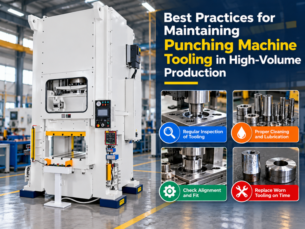
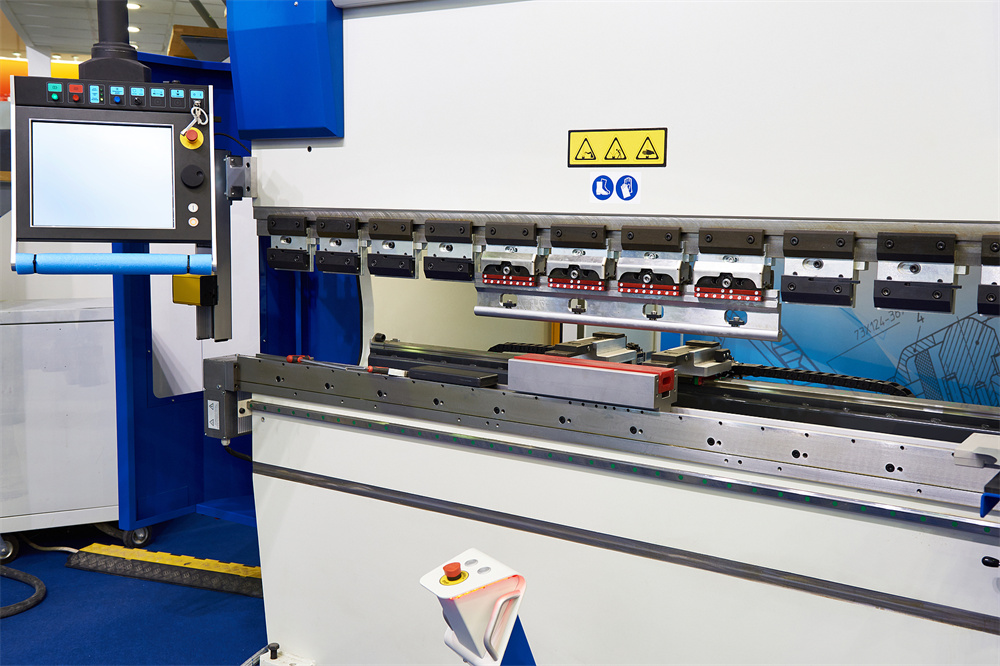
In the world of precision metal fabrication, the press brake is a cornerstone of production. However, even the most advanced HARSLE CNC synchronized hydraulic press brake is only as effective as the tooling it utilizes. Press brake tooling—comprising the punch (upper tool) and the die (lower tool)—is subjected to immense pressure, friction, and heat during every cycle. Over time, these forces inevitably lead to wear and tear. Understanding the common press brake tool wear signs when replace tooling is essential for maintaining the tight tolerances required in modern manufacturing.
Tooling wear is not merely a cosmetic issue; it directly impacts the geometry of the finished part. When a punch tip rounds off or a die shoulder deforms, the bend angle becomes inconsistent, and the inside radius of the part changes. This leads to increased scrap rates, wasted material, and potential damage to the machine itself. High-quality tooling is typically made from hardened tool steel or 42CrMo alloy, often heat-treated to 45-50 HRC. Despite this hardness, the repetitive nature of bending high-tensile materials like stainless steel or armored plate accelerates the degradation process.
Furthermore, the physics of the bending process involves significant sliding friction. As the workpiece is forced into the die, it slides across the die shoulders. This friction generates heat and can cause material transfer, known as galling. If left unaddressed, this wear pattern becomes self-reinforcing, leading to rapid tool failure. For operators and shop managers, recognizing the early indicators of wear is the difference between a productive shift and a costly breakdown.
In this guide, we will explore the technical parameters that define tool health, the specific signs that indicate it is time for a replacement, and the engineering calculations used to predict tool life. By implementing a proactive maintenance and replacement strategy, fabrication shops can ensure the longevity of their HARSLE equipment and the quality of their output.
Core Parameters of Press Brake Tooling Health
To accurately assess when to replace tooling, one must understand the core parameters that define a tool’s functional integrity. These parameters are measurable and provide an objective basis for replacement decisions. The first and most critical parameter is the Punch Tip Radius. In air bending, the punch tip radius determines the inside bend radius of the part. If the tip becomes flattened or chipped, the resulting bend will be irregular, often leading to “springback” issues that the CNC controller cannot easily compensate for.
The second parameter is the Die Shoulder Radius. The shoulders of the V-die are the primary contact points for the workpiece. As these shoulders wear down, the effective V-opening width changes. A wider V-opening results in a larger bend radius and a different tonnage requirement. Even a wear of 0.1mm on the shoulders can significantly alter the bend angle across a long workpiece, leading to the dreaded “bowing” effect where the center of the part is bent differently than the ends.
Another vital parameter is Surface Hardness. While tools are hardened during manufacturing, excessive heat or improper use can lead to localized annealing, softening the steel. Once the surface hardness drops, the rate of wear increases exponentially. Operators should also monitor the Parallelism of the Tooling. Over years of use, the base of the punch or the seat of the die can become uneven due to debris or localized overloading, leading to misalignment during the stroke.
Finally, Surface Finish plays a role in both part quality and tool life. A smooth, polished surface reduces friction and prevents galling. When the surface becomes pitted or scratched, it creates friction points that catch the material, causing marks on the workpiece and increasing the force required for the bend. Monitoring these parameters through regular inspections with micrometers, radius gauges, and hardness testers is the first step in a professional maintenance program.
Calculation Method: Estimating Tool Life and Tonnage Limits
Predicting when a tool will fail or require replacement involves both empirical observation and mathematical calculation. The most common calculation used in the industry is the Tonnage Limit Calculation. Every tool has a maximum load capacity, usually expressed in tons per meter (T/m). Exceeding this limit causes plastic deformation of the tool, leading to immediate and permanent wear.
The formula for calculating the required tonnage for a V-bend is: P = (650 * S^2 * L) / V, where P is the force in kilonewtons, S is the material thickness, L is the length of the bend, and V is the V-opening width. If the calculated P exceeds the rated capacity of the tool, the tool is being overstressed. Repeatedly operating at 90% or more of a tool’s rated capacity will shorten its lifespan by up to 50% compared to operating at 60-70% capacity.
Another method for estimating tool life is the Cycle Count Tracking. High-end CNC systems, like those found on HARSLE machines, can track the number of strokes performed with specific tool sets. For standard hardened steel tooling, a typical lifespan might be 500,000 to 1,000,000 cycles depending on the material being bent. When bending abrasive materials like hot-rolled steel with mill scale, the cycle life may drop significantly. By dividing the total expected cycles by the average daily production, managers can forecast replacement dates months in advance.
Lastly, the Wear Gradient Calculation involves measuring the tool at specific intervals (e.g., every 50,000 cycles). By plotting the reduction in tip radius or shoulder height over time, engineers can determine the “wear rate.” When the wear rate begins to accelerate—a phenomenon known as the “wear knee”—it indicates that the tool’s structural integrity is compromised and replacement is imminent. This data-driven approach removes the guesswork from maintenance schedules.
Parameter Table: Tooling Wear Limits and Specifications
The following table provides a reference for common tooling specifications and the thresholds at which wear becomes critical. These values are general guidelines for standard industrial applications.
| Parameter | Standard Specification | Critical Wear Limit | Impact of Deviation |
|---|---|---|---|
| Punch Tip Radius | 0.2mm – 6.0mm (Typical) | >10% Deviation from Nominal | Inconsistent inside radius, cracking in bend |
| Die Shoulder Radius | R1.0 – R5.0 (Based on V-width) | Visible flattening or >0.15mm wear | Angle variation, increased tonnage needed |
| Surface Hardness | 45 – 52 HRC | <40 HRC | Rapid deformation, galling, and pitting |
| Tool Straightness | +/- 0.02mm per meter | >0.1mm per meter | “Crowning” issues, uneven bend angles |
| Surface Roughness (Ra) | 0.8 μm – 1.6 μm | >3.2 μm | Workpiece marking, high friction |
Common Engineering Mistakes in Tooling Management
One of the most frequent mistakes in metal fabrication is using worn tooling to “save money.” While it may seem economical to delay a $2,000 tooling purchase, the hidden costs are staggering. Worn tools require more setup time as operators struggle to achieve the correct angle. They also lead to higher scrap rates. If a single batch of stainless steel parts is ruined due to inconsistent bending, the cost of the lost material often exceeds the cost of the new tool. Furthermore, worn tools require higher tonnage to achieve the same bend, which puts unnecessary strain on the press brake’s hydraulic seals and frame.
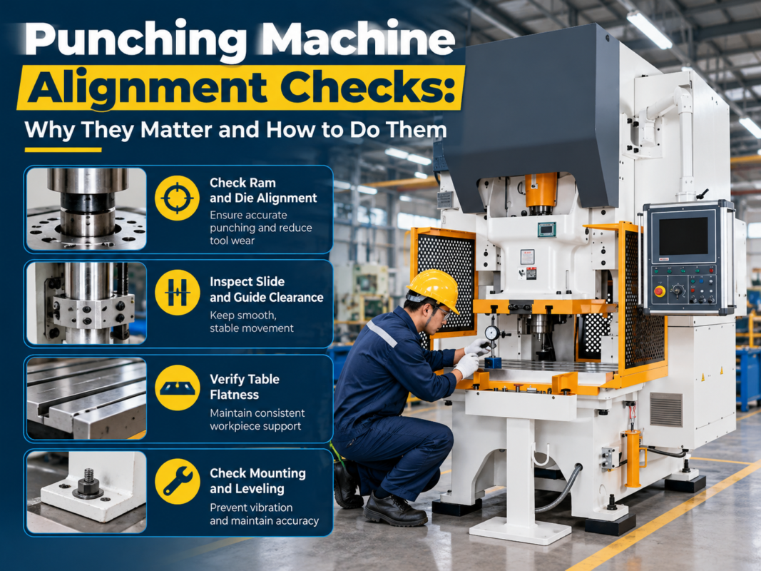
Another common error is improper tool alignment. Even brand-new tooling will wear prematurely if the punch and die are not perfectly centered. Misalignment causes side-loading, which can chip the edges of the punch or cause uneven wear on one side of the die V-opening. Modern HARSLE machines feature precision clamping systems to mitigate this, but manual checks are still necessary, especially after a tool change or a minor collision.
Neglecting to clean the material is a third major mistake. Bending material with heavy mill scale, rust, or laser dross acts like sandpaper on the tooling. The abrasive particles embed themselves into the die shoulders, grinding away the precision-machined surfaces. Operators should always wipe down the material or use a protective film (like Nitto tape) when bending sensitive or abrasive parts. Similarly, failing to lubricate the die shoulders increases friction and heat, accelerating the wear process.

Finally, many shops fail to match the tool to the material. Using a standard punch to bend high-strength AR400 steel will result in immediate tip deformation. Specialized materials require specialized tooling with specific radii and hardening treatments. Attempting to “force” a tool to perform a job it wasn’t designed for is a recipe for rapid wear and potential safety hazards, such as tool shattering under extreme pressure.
Selection Checklist: When and How to Replace Tooling
When the common press brake tool wear signs when replace tooling become evident, follow this checklist to ensure you select the right replacements and maintain your HARSLE machine’s performance:
- Visual Inspection: Check for visible “shining” on die shoulders (indicating wear), chips on the punch tip, or deep scratches in the V-groove.
- Tolerance Audit: If you find yourself constantly adjusting the CNC offset to achieve the same angle, the tool geometry has likely changed.
- Material Compatibility: Are you moving to harder materials? If so, consider upgrading to nitrided or laser-hardened tooling for better wear resistance.
- Sectionalized vs. Full Length: Consider replacing long, solid tools with sectionalized tooling. This allows you to replace only the worn segments in the future, saving costs.
- Clamping System Check: Ensure the new tooling is compatible with your current clamping system (e.g., Amada/Promecam, New Standard, or American Tang).
- Tonnage Rating Verification: Always verify that the new tool’s T/m rating exceeds your most demanding application by at least 20%.
- Surface Treatment: For bending stainless steel or aluminum without marking, look for tooling with specialized coatings or polished radii.
- Supplier Reliability: Source tooling from reputable manufacturers like HARSLE to ensure the steel quality and heat treatment meet industrial standards.
FAQ: Frequently Asked Questions About Press Brake Tooling
1. How often should I inspect my press brake tooling?
For high-volume production, a quick visual inspection should be performed daily. A detailed measurement of the punch tip and die shoulders should be conducted monthly or every 100,000 cycles. If you notice a sudden change in part accuracy, inspect the tooling immediately.
2. Can worn press brake tools be reground?
Yes, many types of tooling can be reground to restore their geometry. However, this process reduces the overall height of the tool, which must be accounted for in the CNC controller. Additionally, regrinding may remove the hardened surface layer, requiring the tool to be re-heat-treated, which can sometimes be more expensive than buying new tools.
3. What causes “galling” on the die shoulders?
Galling occurs when the workpiece material (usually soft metals like aluminum or galvanized steel) cold-welds itself to the die shoulder due to high pressure and friction. This can be prevented by using lubricants, polished dies, or protective bending tapes.
4. Does the type of material I bend affect tool wear?
Absolutely. Stainless steel is much harder and more abrasive than mild steel, leading to faster wear. Aluminum is softer but prone to galling. Materials with mill scale are the most abrasive and will wear down die shoulders very quickly if not cleaned.
5. How do I know if my punch is overloaded?
Signs of overloading include permanent deformation (the punch becomes shorter), cracking at the base or the tip, and the punch “seating” too deeply into the ram. Always check the tonnage charts provided by the manufacturer before starting a job.
6. Why is my bend angle inconsistent across the length of the part?
This is often a sign of uneven wear on the die shoulders or a loss of parallelism in the tooling. It can also be caused by the “bowing” of the machine frame, but if the machine is properly crowned, the tooling is the most likely culprit.
By staying vigilant and recognizing the common press brake tool wear signs when replace tooling, you can maintain the high standards of precision and efficiency that HARSLE machinery is known for. Investing in quality tooling and timely replacements is the most effective way to protect your equipment and your bottom line.