Hydraulic Press Components Explained: Frame, Cylinder, Pump, and Control System

Technical Overview of Hydraulic Press Systems
A hydraulic press is a cornerstone of modern metal fabrication, utilizing Pascal’s Principle to generate massive amounts of force through the medium of pressurized fluid. At HARSLE, we understand that the efficiency of a hydraulic press is not determined by a single part, but by the harmonious integration of its core components: the frame, the cylinder, the pump, and the control system. Each of these elements must be engineered to withstand extreme stresses while maintaining precision over thousands of cycles.
The frame provides the structural skeleton, ensuring that the force generated is directed entirely toward the workpiece without causing structural deformation. The hydraulic cylinder acts as the muscle, converting fluid energy into linear mechanical force. The pump serves as the heart, circulating hydraulic oil at specific pressures and flow rates. Finally, the control system acts as the brain, orchestrating the movement, timing, and safety protocols of the entire operation. Understanding these components is vital for any engineer or facility manager looking to optimize production and ensure equipment longevity.
The Structural Foundation: The Frame
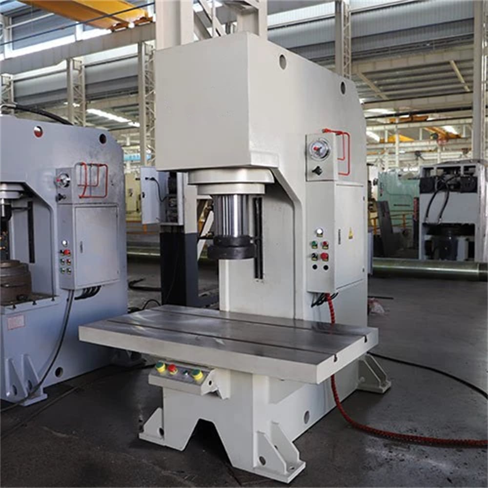
The frame of a hydraulic press is its most visible and arguably most critical structural component. It must be rigid enough to resist the deflection forces generated during high-tonnage operations. There are several common frame designs, each suited for specific applications. The C-frame (or Gap-frame) press offers three-sided access, making it ideal for smaller parts and manual loading. However, because of its asymmetrical design, it is more prone to ‘yaw’ or deflection under maximum load.
In contrast, the H-frame (or Four-Column) press provides a much more stable and balanced environment. The four-column design ensures that the bolster and slide remain perfectly parallel, which is essential for high-precision die work. HARSLE utilizes high-grade Q235B or Q345B steel plates, which are precision-welded and then subjected to vibration or thermal stress relief to ensure that the frame does not warp over time. A robust frame is the primary defense against tool wear and part inaccuracy.
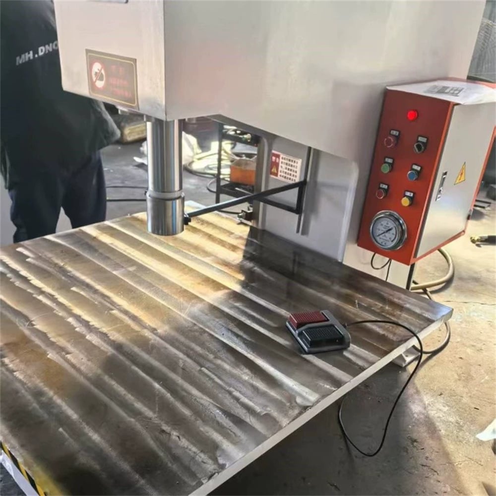
The Powerhouse: The Hydraulic Cylinder
The hydraulic cylinder is where the ‘work’ happens. It consists of a cylindrical barrel, a piston, and a piston rod. When high-pressure oil enters the cylinder, it pushes against the piston, extending the rod and the attached slide (ram). The quality of the cylinder’s internal surfaces is paramount; HARSLE cylinders are typically honed to a mirror finish to reduce friction and prevent seal degradation. The seals themselves are high-performance components, often sourced from brands like NOK or SKF, designed to prevent internal and external leakage even under pressures exceeding 300 bar.
Cylinders can be single-acting (using gravity or springs for the return stroke) or double-acting (using hydraulic pressure for both extension and retraction). For metal fabrication, double-acting cylinders are standard because they allow for controlled retraction speeds and the ability to pull dies apart. The rod is usually hard-chrome plated to resist corrosion and mechanical scratching, which are the leading causes of seal failure in industrial environments.
The Circulatory System: The Hydraulic Pump
The hydraulic pump converts mechanical energy from an electric motor into hydraulic energy. In the context of HARSLE machinery, we often utilize high-pressure piston pumps or internal gear pumps. Piston pumps are favored for high-pressure applications (up to 31.5 MPa) due to their high efficiency and durability. Gear pumps, while simpler, are often used in auxiliary circuits or lower-pressure systems due to their lower cost and quieter operation.
Modern hydraulic presses often incorporate variable displacement pumps. These pumps can adjust the volume of oil they move per cycle, allowing the press to move quickly during the ‘approach’ phase and then slow down for the ‘pressing’ phase without wasting energy. This not only improves cycle times but also significantly reduces the heat generated within the hydraulic oil, extending the life of the fluid and the components it lubricates.
The Intelligence: The Control System
The control system has evolved from simple manual levers to sophisticated PLC (Programmable Logic Controller) and CNC (Computer Numerical Control) interfaces. A modern HARSLE hydraulic press features a touchscreen HMI (Human Machine Interface) that allows operators to set parameters such as stroke length, pressure dwell time, and approach speeds. The control system monitors sensors throughout the machine, including pressure transducers and linear encoders, to ensure that the press operates within its safety and performance envelopes.
Safety is a major component of the control system. This includes light curtains, dual-hand tie-down controls, and emergency stop circuits. Furthermore, advanced control systems now include diagnostic tools that can alert maintenance teams to filter clogs, overheating, or pressure drops before they lead to catastrophic failure. Integration with Industry 4.0 allows these machines to report production data directly to factory management systems.
Core Parameters of Hydraulic Presses
When evaluating a hydraulic press, several core parameters define its capability and suitability for a specific task. These parameters are interconnected; changing one often necessitates adjustments in others to maintain system balance.
- Nominal Force (Tonnage): The maximum pressure the press can exert. This is the most common way to categorize presses (e.g., a 100-ton press).
- Stroke Length: The total distance the ram can travel from its fully retracted position to its fully extended position.
- Daylight (Open Height): The vertical distance between the bolster plate and the ram when it is fully retracted. This determines the maximum height of the tooling and workpiece.
- Approach and Pressing Speeds: The speed at which the ram moves. High approach speeds save time, while controlled pressing speeds are necessary for quality metal forming.
- Bolster Dimensions: The surface area available for mounting dies. A larger bolster allows for larger workpieces but requires a more rigid frame to prevent deflection.
Calculation Method for Hydraulic Force
Calculating the force of a hydraulic press is a fundamental engineering task. The force generated is a product of the pressure provided by the pump and the surface area of the piston inside the cylinder. The formula is expressed as:
Force (F) = Pressure (P) × Area (A)
To calculate the Area (A) of a circular piston, use the formula: A = π × r² (where r is the radius of the piston). For example, if a cylinder has a piston diameter of 200mm (radius of 10cm) and the system pressure is 250 bar (approx. 255 kg/cm²):
- Calculate Area: A = 3.14159 × 10² = 314.16 cm²
- Calculate Force: F = 255 kg/cm² × 314.16 cm² = 80,110 kg
- Convert to Tons: 80,110 kg / 1000 = 80.11 Metric Tons
It is also important to calculate the Motor Power required to drive the pump. This is calculated using the flow rate (Q) and pressure (P): Power (kW) = (Pressure (bar) × Flow (L/min)) / 600. This ensures the electric motor is not undersized, which would lead to overheating and premature failure.
Hydraulic Press Parameter Table
| Model Type | Nominal Force (kN) | Stroke (mm) | Max Pressure (MPa) | Motor Power (kW) | Application |
|---|---|---|---|---|---|
| HARSLE Y32-100 | 1000 | 500 | 25 | 7.5 | Small part stamping/forming |
| HARSLE Y32-315 | 3150 | 700 | 25 | 15 | Deep drawing, heavy bending |
| HARSLE Y32-500 | 5000 | 800 | 25 | 22 | Automotive panel forming |
| HARSLE Y32-1000 | 10000 | 1000 | 31.5 | 45 | Heavy industrial forging |
Common Engineering Mistakes in Hydraulic Press Operation
Even the best machinery can fail if operated or maintained incorrectly. One of the most common mistakes is ignoring oil cleanliness. Hydraulic systems are incredibly sensitive to particulates. Contaminated oil acts like liquid sandpaper, eroding the precision surfaces of the pump and the cylinder seals. Implementing a strict filtration and oil analysis schedule is non-negotiable for high-uptime environments.
Another frequent error is off-center loading. Hydraulic presses are designed to apply force vertically. If a die is placed off-center, it creates a ‘side load’ on the ram and cylinder. This causes uneven wear on the bushings and can eventually lead to a bent piston rod or a cracked cylinder gland. Always ensure the center of pressure of the tooling aligns with the center of the ram.
Finally, many operators neglect the cooling system. As hydraulic fluid passes through valves and orifices, it generates heat. If the oil temperature exceeds 60°C (140°F), the viscosity drops, leading to increased internal leakage and rapid seal degradation. Ensuring that heat exchangers are clean and that the cooling water or air flow is sufficient is critical during summer months or high-cycle production runs.
Selection Checklist for Buyers
Choosing the right hydraulic press requires a deep understanding of your production needs. Use this checklist to guide your decision-making process:
- Tonnage Requirement: Have you calculated the maximum force needed for your thickest material and most complex die? (Always add a 20% safety margin).
- Frame Style: Do you need the accessibility of a C-frame or the precision/rigidity of an H-frame?
- Stroke and Daylight: Will your largest die set fit within the open height, and does the ram have enough travel to clear the part?
- Speed Requirements: Does the press meet your cycle time targets? Consider a machine with a ‘fast approach’ valve.
- Control Complexity: Do you need a simple manual setup, or a CNC system with recipe storage for frequent tool changes?
- Safety Features: Does the machine comply with local safety standards (CE, OSHA, etc.)? Are light curtains and interlocks included?
- Maintenance Access: Are the pump, filters, and valves easily accessible for routine servicing?
- Manufacturer Reputation: Does the supplier (like HARSLE) provide robust after-sales support and spare parts availability?
Frequently Asked Questions (FAQ)
1. How often should I change the hydraulic oil?
Generally, hydraulic oil should be changed every 2,000 to 4,000 hours of operation, or at least once a year. However, this depends on the environment. In dusty or high-heat conditions, more frequent changes or constant filtration may be necessary. Always check the oil’s color and clarity regularly.
2. Why is my hydraulic press losing pressure?
Pressure loss is usually caused by internal leakage. This could be due to worn piston seals in the cylinder, a failing bypass valve, or wear within the hydraulic pump. Check for external leaks first, then use a flow meter to diagnose which component is bypassing fluid.
3. Can I use a hydraulic press for high-speed stamping?
While hydraulic presses are known for their power and control, they are generally slower than mechanical presses. However, modern ‘high-speed’ hydraulic presses with advanced servo-hydraulics can achieve impressive cycle rates that are sufficient for many stamping applications while offering better control over the stroke.
4. What is the difference between a 4-column and a mono-block frame?
A 4-column frame uses four distinct pillars to guide the ram, offering excellent access but requiring careful maintenance of the bushings. A mono-block (or side-plate) frame is a solid welded structure that offers maximum rigidity and is often used for extremely high-tonnage applications where deflection must be near zero.
5. How do I prevent the hydraulic system from overheating?
Ensure the cooling system (air or water-cooled) is functioning correctly. Check that the relief valves are not set too low, which causes the pump to dump high-pressure oil back to the tank, generating heat. Also, ensure the oil level is correct, as the tank itself acts as a heat sink.


