Hydraulic Press Maintenance Guide: Preventing Downtime and Extending Service Life

Technical Overview of Hydraulic Press Systems
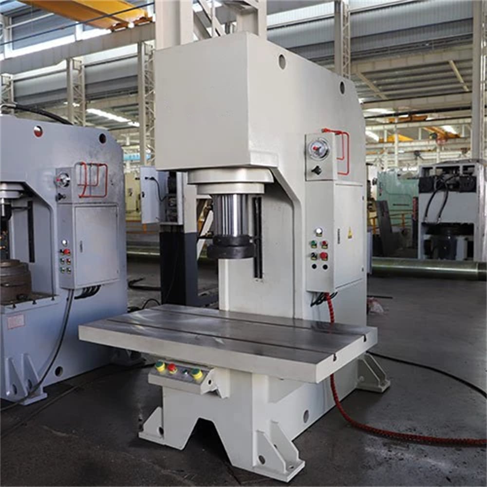
The hydraulic press is a cornerstone of modern metal fabrication, utilizing Pascal’s Principle to generate massive compressive forces. At its core, the system consists of a hydraulic pump, a series of control valves, high-pressure cylinders, and a robust frame. Maintenance is not merely a chore; it is a critical engineering requirement to ensure that the fluid power is transmitted efficiently and safely. Without a rigorous Hydraulic Press Maintenance : Preventing Downtime Extending Service Life strategy, the precision of the machine degrades, leading to rejected parts and costly operational halts.
Hydraulic systems operate under extreme pressures, often exceeding 3000 PSI (210 bar). This pressure places immense stress on seals, hoses, and structural components. The hydraulic fluid serves multiple purposes: it transmits power, lubricates moving parts, and dissipates heat. Over time, this fluid can become contaminated with microscopic metal shavings, moisture, and chemical breakdown products. This contamination is the primary cause of component failure in hydraulic presses. Understanding the interplay between fluid dynamics and mechanical wear is the first step in a professional maintenance program.
Furthermore, the structural integrity of the press frame—whether it is an H-frame, C-frame, or four-column design—must be monitored. Stress fractures or misalignment can lead to uneven pressure distribution, which not only ruins the workpiece but can also cause catastrophic failure of the main cylinder. A well-maintained press ensures that the ram moves perfectly perpendicular to the bolster plate, maintaining the tight tolerances required in aerospace, automotive, and appliance manufacturing.
Modern HARSLE hydraulic presses incorporate advanced PLC controls and monitoring sensors. These systems can provide early warnings of pressure drops or temperature spikes. However, the human element of inspection remains irreplaceable. A technician’s ability to hear the subtle whine of a cavitating pump or feel the excessive heat on a valve block is often the first line of defense against major downtime. By integrating digital monitoring with physical inspections, manufacturers can achieve a state of ‘predictive maintenance’ rather than ‘reactive repair’.
Core Parameters for Maintenance Monitoring
To effectively manage Hydraulic Press Maintenance : Preventing Downtime Extending Service Life, operators must track specific technical parameters. The most critical of these is the hydraulic oil temperature. Most industrial presses are designed to operate between 40°C and 55°C (104°F to 131°F). If the temperature exceeds 60°C, the oil begins to oxidize rapidly, losing its lubricating properties and causing seals to harden and leak. Conversely, if the oil is too cold, its viscosity increases, leading to sluggish performance and potential pump cavitation.
Another vital parameter is the filtration rating, usually measured in microns. High-precision valves often require oil filtered to 10 microns or better. Monitoring the pressure differential across the oil filter is a standard practice; a high differential indicates a clogged filter that is bypassing oil, allowing contaminants to circulate through the sensitive piston and valve assemblies. Regular oil analysis (spectrography) should be conducted to check for the presence of iron, copper, and silicon, which indicate internal wear or external contamination.
Ram speed and cycle time are also key indicators of system health. If the approach speed or the pressing speed begins to drift from the factory specifications, it usually points to internal leakage in the cylinder or a failing pump. Similarly, the ‘dwell time’—the ability of the press to hold a specific pressure without the pump running constantly—is a direct measure of the integrity of the check valves and cylinder seals. Any deviation in these parameters should trigger an immediate technical review.
Calculation Method for Maintenance Diagnostics
Engineering-grade maintenance involves more than just visual checks; it requires calculation to diagnose the root cause of performance issues. One of the most fundamental calculations is determining the actual force being exerted by the press. The formula is F = P × A, where F is the force (in Newtons or Pounds), P is the hydraulic pressure (in Pascals or PSI), and A is the effective area of the cylinder piston. If the calculated force does not match the output measured by a load cell, there is likely an internal bypass occurring within the cylinder.
To calculate the required cooling capacity for the hydraulic system, engineers use the formula: Heat Load (kW) = Total Input Power (kW) × (1 – Efficiency). Most hydraulic systems are roughly 70-80% efficient, meaning 20-30% of the motor’s power is converted directly into heat. If the cooling system (air or water-cooled) cannot dissipate this calculated heat load, the oil will overheat, leading to the degradation mentioned earlier. Ensuring the heat exchanger is clean and the coolant flow rate is correct is a mathematical necessity for long-term operation.
Furthermore, calculating the ‘Volumetric Efficiency’ of the pump can reveal wear before the pump fails completely. This is done by comparing the theoretical flow rate (Displacement × RPM) with the actual flow rate measured at the system’s working pressure. A drop in volumetric efficiency below 85% typically indicates that the internal clearances in the pump have increased due to wear, and the pump should be scheduled for refurbishment or replacement during the next planned maintenance window.
Hydraulic Press Maintenance Parameter Table
| Maintenance Task | Frequency | Parameter/Target | Action if Out of Spec |
|---|---|---|---|
| Oil Temperature Check | Daily | 40°C – 55°C | Check cooling system/heat exchanger |
| Oil Level Inspection | Daily | Sight glass 3/4 full | Top up with filtered ISO VG 46/68 |
| Filter Differential Pressure | Weekly | < 25 PSI (1.7 bar) | Replace filter element immediately |
| Ram Parallelism Check | Monthly | < 0.05mm per 300mm | Adjust gibs or re-level the press |
| Oil Analysis (Lab) | Quarterly | ISO 4406 16/14/11 | Perform off-line filtration or oil change |
| Accumulator Pre-charge | Bi-Annually | 90% of working pressure | Recharge with Dry Nitrogen |
| Structural Bolt Torque | Annually | Per Manufacturer Spec | Tighten using calibrated torque wrench |
Common Engineering Mistakes in Press Maintenance
One of the most frequent mistakes in Hydraulic Press Maintenance : Preventing Downtime Extending Service Life is the use of incorrect hydraulic fluid. Many operators assume that any “hydraulic oil” will suffice. However, modern high-speed presses require specific additives for anti-wear (AW), anti-foaming, and high viscosity index (VI). Mixing different brands or grades of oil can lead to chemical incompatibility, resulting in the formation of ‘varnish’—a sticky residue that jams valves and coats heat exchangers, significantly reducing cooling efficiency.
Another common error is neglecting the air breather on the hydraulic reservoir. As the ram moves, air is drawn into and pushed out of the tank. If the breather is clogged or of poor quality, it can create a vacuum in the tank, leading to pump cavitation. If it lacks a desiccant, it allows atmospheric moisture to enter the system. Water in hydraulic oil causes the oil to turn milky, promotes rust on internal components, and leads to a phenomenon called ‘hydrogen embrittlement’ in high-strength steel parts, which can cause sudden structural failure.
Improper ‘bleeding’ of the system after a component change is also a major issue. Air trapped in the hydraulic circuit is compressible, unlike hydraulic fluid. This leads to ‘spongy’ operation, erratic ram movement, and ‘dieseling’—where air bubbles explode under high pressure, causing localized temperatures high enough to burn the oil and damage seal surfaces. Engineers must ensure that all air is purged from the highest points of the system and from the cylinder bleed ports before returning the machine to full production.
Finally, many maintenance teams overlook the importance of the press ‘gibs’ or guides. These are the mechanical slides that ensure the ram moves straight. If they are not lubricated or are adjusted too tightly, they generate excessive heat and friction, overloading the hydraulic system. If they are too loose, the ram will tilt during the stroke, causing ‘side loading’ on the cylinder seals and rod, leading to premature leaks and potential scoring of the cylinder walls.
Selection Checklist for a Maintainable Hydraulic Press
When purchasing a new machine, such as those offered by HARSLE, it is vital to select a model designed with maintenance in mind. A machine that is difficult to service will inevitably be neglected. Use the following checklist during the selection process:
- Accessibility: Are the pumps, motors, and valve manifolds easily accessible, or are they buried deep inside the frame?
- Filtration System: Does the press include a high-quality return-line filter and a separate kidney-loop filtration system for continuous cleaning?
- Monitoring Sensors: Does the PLC provide real-time data on oil temperature, pressure, and filter status with alarm history?
- Standardized Components: Does the manufacturer use reputable brands for valves and seals (e.g., Rexroth, Parker, Vickers) that are easily sourced locally?
- Cooling Capacity: Is the heat exchanger oversized for the environment? (Crucial for hot climates or high-cycle applications).
- Diagnostic Ports: Are there dedicated pressure test points throughout the circuit to allow for easy troubleshooting without breaking lines?
- Documentation: Does the machine come with a detailed hydraulic schematic, a clear maintenance schedule, and a comprehensive spare parts list?
Frequently Asked Questions (FAQ)
1. How often should I change the hydraulic oil in my press?
There is no fixed time frame, as it depends on the environment and usage. However, a general rule is every 2,000 to 4,000 operating hours. The best practice is to perform quarterly oil analysis and only change the oil when the additive package is depleted or contamination levels exceed the ISO 4406 cleanliness target for your specific valves.
2. Why is my hydraulic press making a loud banging noise?
A loud banging or ‘hammering’ noise is often caused by ‘hydraulic shock.’ This occurs when the flow of oil is stopped or redirected too suddenly, creating a pressure wave. This can be caused by a faulty accumulator, an improperly adjusted relief valve, or air trapped in the system. It should be addressed immediately as it can crack manifolds and fatigue welds.
3. What causes the ram to drift down when the press is stopped?
Ram drift is usually caused by internal leakage. This could be oil bypassing the piston seals inside the cylinder or a leaking check valve/directional valve in the manifold. To diagnose, you can safely block the ram and check if the pressure holds in the cylinder’s upper chamber.
4. Can I use a higher viscosity oil to stop leaks?
No, this is a temporary ‘band-aid’ that causes more harm than good. Thicker oil increases internal friction, raises operating temperatures, and may not flow fast enough to lubricate the pump properly. The correct solution is to identify the source of the leak and replace the worn seals or O-rings.
5. How do I know if my pump is cavitating?
Cavitation produces a distinct high-pitched ‘marbles in a blender’ sound. It happens when the pump cannot get enough oil, causing vacuum bubbles to form and then implode violently. Check for a clogged suction strainer, a closed suction valve, or an air leak in the suction line.
6. Is it necessary to check the foundation bolts of the press?
Yes. A hydraulic press generates massive forces that are transmitted to the floor. If the foundation bolts loosen, the press can shift slightly, leading to frame misalignment, vibration, and eventually, structural damage to the machine or the factory floor. Check them annually with a torque wrench.


