Press Brake Safety Maintenance: Key Checks Before Every Shift


The Critical Role of Press Brake Safety Maintenance
In the high-stakes environment of metal fabrication, the press brake stands as a cornerstone of production. However, its immense power requires a disciplined approach to safety and upkeep. Implementing a rigorous routine for Press Brake Safety Maintenance: Key Checks Before Every Shift is not merely a recommendation; it is a fundamental necessity for protecting operators and ensuring the longevity of the equipment. When a machine is properly maintained, it operates with higher precision, experiences less downtime, and maintains a higher resale value over time. HARSLE, a leader in industrial machinery, emphasizes that a proactive maintenance culture starts the moment an operator approaches the machine.
The importance of pre-shift maintenance extends beyond simple mechanical functionality. It encompasses the psychological readiness of the operator and the physical integrity of the workspace. A well-maintained machine is a predictable machine. In metalworking, unpredictability is the primary cause of accidents. By identifying a loose bolt, a leaking hydraulic hose, or a malfunctioning light curtain before the first bend is made, facilities can prevent catastrophic failures that lead to expensive repairs or, worse, workplace injuries. This guide provides a deep dive into the essential protocols every shop should adopt to ensure their press brakes remain in peak condition.
Furthermore, consistent maintenance records are often required for insurance compliance and ISO certifications. By documenting these daily checks, companies build a history of care that proves their commitment to safety standards. This documentation also helps in identifying recurring issues, allowing maintenance teams to address root causes rather than just symptoms. Whether you are operating a manual hydraulic press or a sophisticated multi-axis CNC synchronized press brake, the principles of safety maintenance remain the same: observe, verify, and act.
Pre-Shift Daily Inspection: The First Line of Defense
The daily inspection is the most effective way to catch minor issues before they escalate into major problems. This process should begin with a visual sweep of the entire machine and the surrounding area. Operators should look for any obstructions on the floor, such as scrap metal or oil spills, which could cause slips or interfere with the foot pedal operation. The workspace must be clear, well-lit, and organized to facilitate safe movement around the machine. A cluttered environment is a hazard that can distract an operator during critical bending sequences.
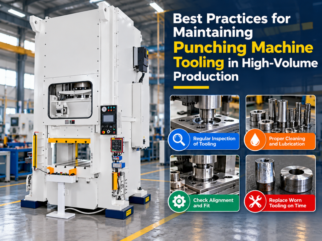
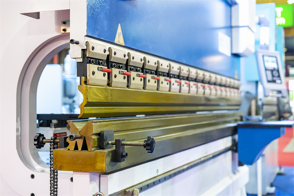
Next, the operator must inspect the tooling. The upper punch and lower die should be checked for cracks, chips, or excessive wear. Even a small deformation in the tooling can lead to inaccurate bends or, in extreme cases, tool breakage under pressure. Ensure that the tooling is properly seated and clamped. Loose tooling can shift during the stroke, leading to machine damage or operator injury. If the machine uses a sectionalized tooling system, verify that all segments are aligned and securely fastened. This is also the time to ensure that the tooling is appropriate for the material thickness and type being processed during the shift.
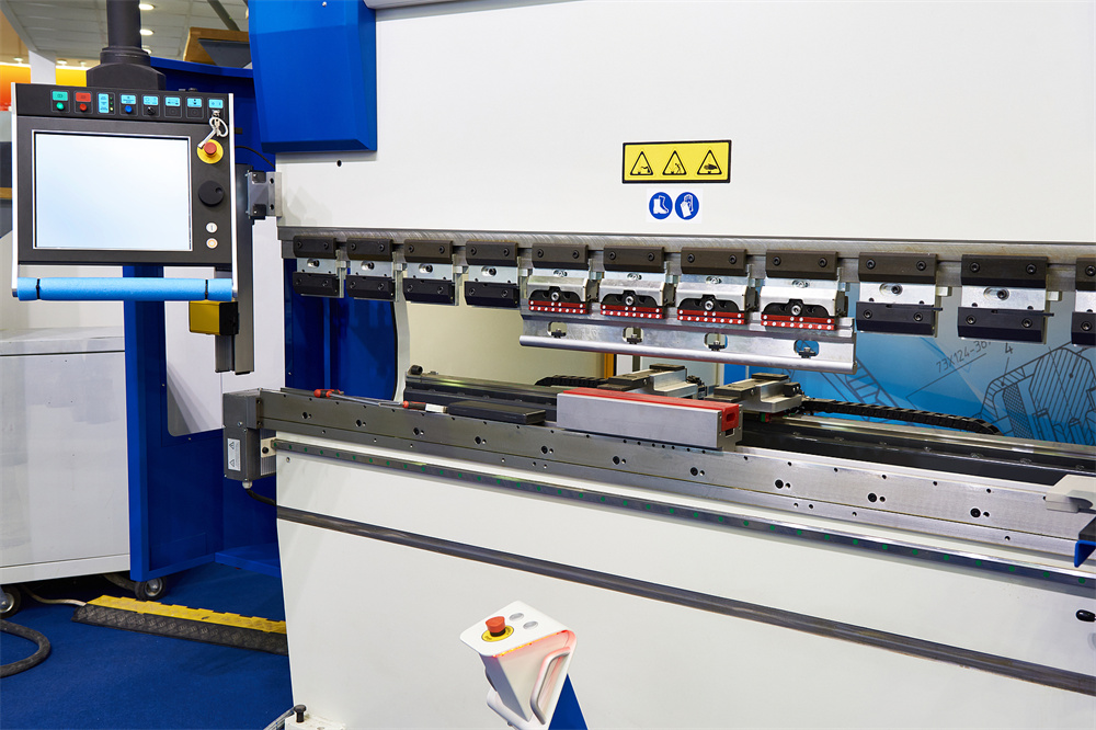
Safety devices are the next priority. Modern press brakes are equipped with advanced safety systems such as laser guards or light curtains. These must be tested at the start of every shift. The operator should verify that the machine stops immediately if the safety beam is interrupted. Similarly, the emergency stop buttons—usually located on the control panel and the foot pedal assembly—must be tested for functionality. If any safety device fails to respond correctly, the machine must be locked out and tagged out until a qualified technician can perform repairs. Never bypass safety systems to meet production quotas.
Hydraulic System Integrity: Monitoring Fluid and Pressure
The hydraulic system is the heart of the press brake, providing the force necessary to bend heavy-gauge metal. Maintaining this system is critical for consistent performance. The first check is the oil level. Most machines feature a sight glass on the hydraulic reservoir. The oil should be at the recommended level and appear clear. If the oil is cloudy or milky, it indicates water contamination; if it is dark or smells burnt, it has likely overheated and lost its lubricating properties. Operating with contaminated oil will rapidly degrade the pump and valves, leading to a total system failure.
Leak detection is another vital part of hydraulic maintenance. Operators should inspect all hoses, fittings, and cylinders for signs of weeping or dripping. Even a small leak can lead to a significant drop in pressure and create a fire hazard if the oil contacts hot surfaces. Pay close attention to the seals around the main cylinders. If there is evidence of oil bypassing the seals, it can cause the ram to drift or lose parallelism during the stroke. High-pressure leaks are particularly dangerous, as they can cause fluid injection injuries, which are medical emergencies.
Finally, monitor the hydraulic temperature and pressure gauges during the initial warm-up. The machine should reach a stable operating temperature before full-load production begins. If the pressure fluctuates wildly or the pump makes excessive noise (cavitation), it may indicate air in the lines or a clogged suction filter. Regular filter changes are essential; a clogged filter forces the pump to work harder, increasing wear and energy consumption. HARSLE recommends using high-quality ISO VG 46 or 68 hydraulic oil, depending on the ambient temperature of your facility.
Electrical and Control System Verification
Modern CNC press brakes rely heavily on complex electrical systems to coordinate the movement of the ram and the backgauge. Before starting the shift, the operator should check the control panel for any error messages or warnings. The CNC software should boot up correctly, and all axes (X, R, Z1, Z2, etc.) should be homed or calibrated according to the manufacturer’s instructions. If the backgauge does not home correctly, the resulting parts will be out of tolerance, leading to wasted material and time.
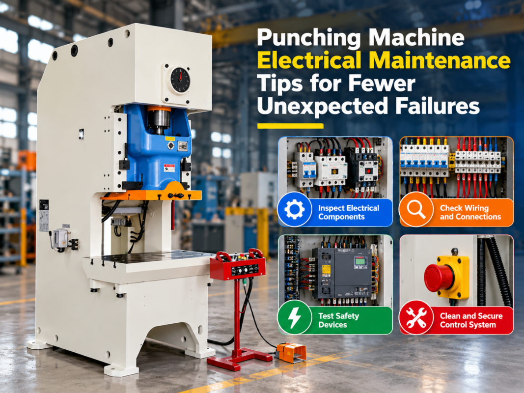
Inspect the electrical cables and conduits for any signs of fraying or damage. In a busy shop, cables can sometimes be pinched by moving parts or damaged by falling scrap. Ensure that all electrical cabinet doors are closed and latched to prevent dust and metal shavings from entering. These contaminants can cause short circuits or overheat sensitive electronic components like PLCs and servo drives. If the machine is equipped with a cooling fan for the electrical cabinet, verify that it is running and that the filters are clean.
The foot pedal and palm buttons are the primary interfaces between the operator and the machine. These should be checked for physical integrity and responsiveness. The foot pedal housing should be sturdy and the protective cover intact to prevent accidental activation. Check the cables connecting the foot pedal to the machine for wear. A faulty foot pedal can lead to unintended ram movement, which is a major safety risk. If the machine uses a two-hand control station, ensure that both buttons must be pressed simultaneously to initiate the stroke, as per safety regulations.
Mechanical Component Stability and Alignment
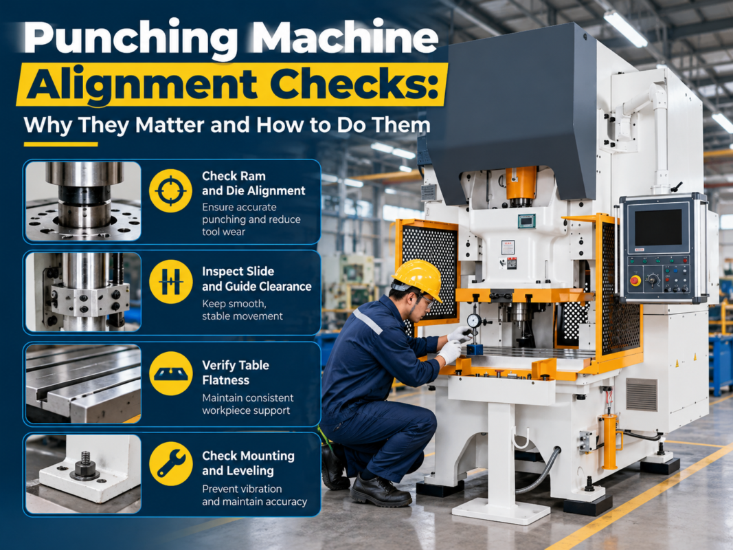
Mechanical stability is what allows a press brake to maintain its accuracy over thousands of cycles. One of the most important mechanical checks is the tightness of all mounting bolts, especially those securing the ram and the bed. The vibration generated during the bending process can gradually loosen these fasteners. A loose bed or ram can lead to misalignment, resulting in uneven bends and increased wear on the machine’s guides. Use a torque wrench to verify that critical bolts meet the manufacturer’s specifications.
The backgauge system is another area that requires close attention. The backgauge fingers should move smoothly along their rails without binding or excessive play. Check the lead screws and linear guides for debris. If metal dust accumulates on these components, it can act as an abrasive, wearing down the precision surfaces. The operator should also verify the alignment of the backgauge fingers relative to the center of the die. If the backgauge is knocked out of alignment—perhaps by a heavy sheet of metal—it must be recalibrated before production continues.
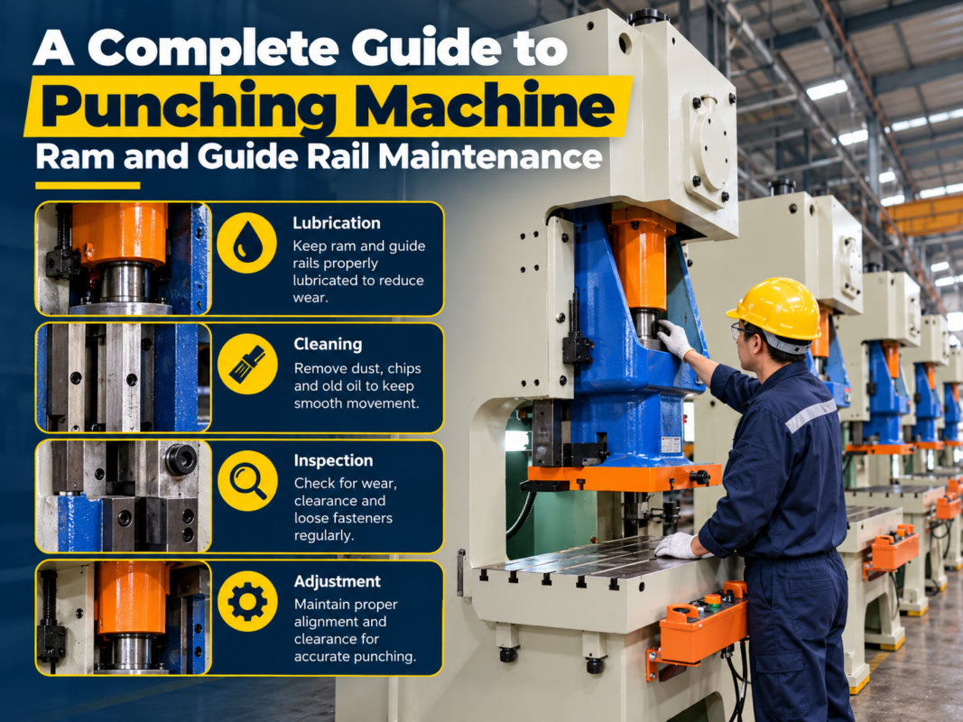
Finally, inspect the ram guides (gibbing). The ram must move vertically with minimal lateral play. If the gibs are too loose, the ram will tilt, causing “ram drift” and inaccurate angles. If they are too tight, they will cause excessive friction and heat, potentially scoring the guide surfaces. Most modern machines have adjustable gibs that can be tuned to maintain the perfect balance between stability and smooth movement. Regular inspection of these guides ensures that the machine’s structural integrity remains intact for years of service.
Developing a Comprehensive Lubrication Plan
Lubrication is the single most important factor in preventing premature wear on a press brake. A comprehensive lubrication plan identifies every moving part that requires grease or oil and specifies the frequency of application. The primary areas requiring lubrication include the ram guides, backgauge lead screws, linear rails, and pivot points on the linkage systems. Without proper lubrication, metal-on-metal contact will quickly destroy precision-ground surfaces, leading to costly repairs and downtime.
Many HARSLE press brakes are equipped with automatic lubrication systems. These systems are designed to deliver a precise amount of lubricant to critical points at set intervals. However, the operator must still check the lubricant reservoir daily to ensure it is full. If the system runs dry, the machine will not be protected. Furthermore, the operator should visually verify that the lubricant is actually reaching the intended points. Sometimes, lubrication lines can become clogged or broken, leaving a component bone-dry despite the pump running.
For machines requiring manual lubrication, a schedule is essential. Use the specific type of grease recommended by the manufacturer—typically a lithium-based grease with extreme pressure (EP) additives. When applying grease, clean the zerk fittings first to avoid pushing dirt into the bearing. Apply enough grease to displace the old, contaminated grease, but avoid over-greasing, which can attract dust and create a messy environment. A clean machine is easier to inspect and maintain, so wipe away any excess lubricant after application.
Recognizing Troubleshooting Signals and Warning Signs
Operators are the first line of defense in identifying problems, as they are most familiar with the machine’s normal sounds and behaviors. Any change in the machine’s “signature” should be investigated immediately. For example, a high-pitched squeal from the hydraulic pump often indicates cavitation or a failing bearing. A deep rhythmic thumping might suggest a problem with the main drive motor or a loose mechanical component. Ignoring these sounds usually leads to a more expensive failure down the road.
Excessive heat is another warning sign. While hydraulic systems get warm during use, they should never be too hot to touch. If the reservoir or the cylinders are radiating intense heat, the system is likely working against a restriction or the oil is bypassing an internal seal. Similarly, check the temperature of the drive motors. Overheating motors can indicate an electrical imbalance or a mechanical bind that is forcing the motor to draw more current than it is rated for.
Vibration and drift are also key indicators of trouble. If the machine vibrates excessively during the stroke, it could be due to air in the hydraulics, loose mounting bolts, or an unbalanced motor. Ram drift—where the ram slowly moves down when the machine is idle—is a serious safety concern usually caused by internal leaking in the hydraulic valves or cylinders. If any of these signals are detected, the operator should stop the machine and report the issue to the maintenance department immediately. Early detection is the key to minimizing repair costs and maximizing uptime.
Press Brake Maintenance Schedule Table
| Frequency | Task Description | Component Focus |
|---|---|---|
| Every Shift | Visual inspection, safety device testing, oil level check. | Tooling, Light Curtains, Reservoir |
| Weekly | Clean backgauge rails, check for loose bolts, inspect hoses. | Mechanical Fasteners, Hydraulics |
| Monthly | Inspect electrical cabinet, clean air filters, check ram parallelism. | Electronics, Cooling, Alignment |
| Every 6 Months | Hydraulic oil analysis, filter replacement, gib adjustment. | Fluid Quality, Wear Surfaces |
| Annually | Full system calibration, comprehensive electrical testing. | CNC Controller, Total Machine Health |
Frequently Asked Questions (FAQ)
1. Why is the hydraulic oil in my press brake turning milky?
Milky oil is a classic sign of water contamination. This can happen due to condensation inside the tank or a leak in a water-cooled heat exchanger. Water reduces the oil’s lubricity and can cause rust inside the hydraulic components. The oil should be changed immediately, and the source of the water ingress must be identified and sealed.
2. How often should I sharpen or replace my press brake tooling?
There is no fixed timeframe, as it depends on the material being bent. Abrasive materials like stainless steel wear tools faster than aluminum. You should inspect tools daily for chips or deformation. If you notice that you need to increase the pressure to achieve the same bend angle, or if the bend radius is becoming inconsistent, it is time to have the tools reground or replaced.
3. What should I do if the light curtain keeps tripping for no reason?
First, ensure the lenses are clean and free of dust or oil film. Check for any physical obstructions or loose mounting brackets that might cause the units to vibrate out of alignment. If the problem persists, it may be an internal electronic fault or a problem with the safety relay. Do not operate the machine until the safety system is functioning reliably.
4. Can I use any type of grease for the backgauge?
No, you should always use the lubricant specified by the manufacturer. Using the wrong grease can lead to gumming, which attracts dirt and increases friction. Most backgauges require a high-quality lithium-based grease. Always clean off the old grease before applying new lubricant to prevent the buildup of abrasive paste.
5. Why does my press brake ram drift down when the power is off?
Ram drift is usually caused by internal leakage in the hydraulic system. This could be a leaking seal in the main cylinders or a faulty check valve in the hydraulic manifold. Because this is a significant safety hazard, the machine should be serviced by a professional technician to ensure the load-holding valves are functioning correctly.
6. How does temperature affect press brake performance?
Hydraulic oil viscosity changes with temperature. If the oil is too cold, the machine may move sluggishly or the pump may cavitate. If the oil is too hot, it becomes too thin, leading to internal leakage and reduced pressure. Most machines have an optimal operating range between 100°F and 120°F (38°C to 49°C). Consistent temperature is key to consistent bend accuracy.