How a Hydraulic Press Works: A Practical Technical Guide for Manufacturers

Technical Overview: The Science Behind Hydraulic Force
Understanding how a hydraulic press works: a practical technical guide for manufacturers begins with a fundamental principle of physics known as Pascal’s Law. This law states that pressure exerted anywhere in a confined incompressible fluid is transmitted equally in all directions throughout the fluid such that the pressure ratio remains the same. In the context of industrial machinery, this allows a small amount of force applied at one point to be transformed into a massive amount of force at another point, making the hydraulic press an indispensable tool in metal fabrication, automotive assembly, and aerospace manufacturing.
At its core, a hydraulic press consists of two cylinders connected to each other, filled with hydraulic fluid (usually a specific grade of oil). One cylinder is small, known as the plunger or slave cylinder, and the other is large, known as the master cylinder or ram. When a pump applies pressure to the fluid in the smaller cylinder, that pressure is transmitted through the piping to the larger cylinder. Because the surface area of the larger piston is significantly greater, the resulting force is multiplied proportionally. This mechanical advantage is what allows a HARSLE hydraulic press to exert hundreds or even thousands of tons of pressure with precision control.
Modern hydraulic presses have evolved far beyond simple two-cylinder systems. Today’s industrial units incorporate complex manifolds, proportional valves, and PLC (Programmable Logic Controller) systems to manage flow rates and pressure timing. The hydraulic circuit is designed to handle high-velocity approach speeds, slow and steady pressing speeds, and rapid retraction. This versatility is why manufacturers prefer hydraulic systems over mechanical ones for deep drawing, molding, and heavy-duty punching operations where consistent force throughout the entire stroke is required.
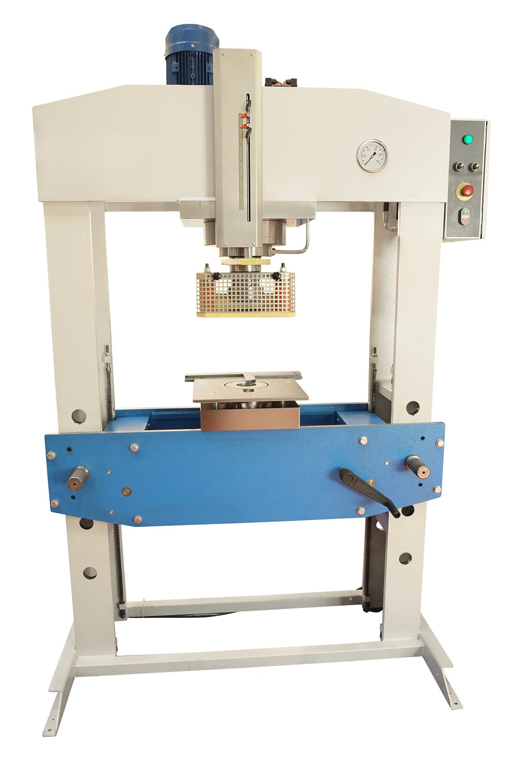
The efficiency of a hydraulic press is also determined by its structural frame. Whether it is a C-frame, H-frame, or a four-column design, the frame must be rigid enough to withstand the immense reactive forces generated during the pressing cycle. Any deflection in the frame can lead to misalignment of the dies, resulting in defective parts and premature wear on the hydraulic seals. Therefore, a practical technical guide for manufacturers must emphasize that the “work” is not just done by the fluid, but by the synergy between fluid dynamics and structural integrity.
Core Parameters of Hydraulic Press Systems
When evaluating how a hydraulic press works: a practical technical manufacturers perspective requires a deep dive into the core parameters that define machine performance. The first and most critical parameter is Tonnage. This is the maximum force the press can exert. Unlike mechanical presses, which reach peak tonnage only at the bottom of the stroke, a hydraulic press can provide full tonnage at any point in the ram’s travel. This makes it ideal for applications like deep drawing where constant pressure is essential for material flow.
The second parameter is the Stroke Length. This defines the total distance the ram can travel from its fully retracted position to its fully extended position. For manufacturers, the stroke length must be sufficient to accommodate the height of the dies and the depth of the part being formed. Adjustable stroke limits are a standard feature in HARSLE machines, allowing operators to minimize cycle times by restricting the ram’s movement to only what is necessary for the specific task.
Daylight (or Open Height) is another vital specification. This refers to the vertical distance between the underside of the ram and the top of the bolster plate when the ram is fully retracted. If the daylight is too small, you won’t be able to fit large molds or dies into the machine. Conversely, excessive daylight might require a longer stroke, which can increase the overall height of the machine and affect the hydraulic cylinder’s stability. Manufacturers must balance daylight requirements with the physical constraints of their workshop floor.
Finally, Speed parameters are divided into three phases: Fast Approach Speed, Pressing Speed, and Fast Return Speed. The fast approach allows the ram to move quickly toward the workpiece to save time. Once the die contacts the material, the system shifts to a slower, controlled pressing speed to ensure the metal deforms correctly without cracking. The fast return speed then resets the ram for the next cycle. Controlling these speeds via variable frequency drives or proportional valves is key to optimizing production throughput.
Calculation Method: Determining Tonnage and Power
To accurately understand how a hydraulic press works: a practical technical manufacturers guide must include the mathematical foundation for force calculation. The basic formula for the force generated by a hydraulic cylinder is: Force (F) = Pressure (P) × Area (A). In this equation, ‘P’ is the hydraulic pressure (usually measured in PSI or Bar) and ‘A’ is the cross-sectional area of the piston head (measured in square inches or square centimeters).
For example, if a hydraulic system operates at 3,000 PSI and has a cylinder with a 10-inch diameter, the area is calculated as πr², which is 3.14159 × 5² = 78.54 square inches. The total force would be 3,000 × 78.54 = 235,620 pounds, or approximately 117.8 tons. Manufacturers must perform these calculations to ensure the press they select has a safety margin—typically 20% above the theoretical force required for the job—to account for friction and material variations.
Beyond force, calculating the Motor Power required to drive the hydraulic pump is essential for electrical planning. The formula is: Power (HP) = (Flow Rate (GPM) × Pressure (PSI)) / 1714. This calculation helps in selecting the right electric motor that can maintain the required flow rate at peak pressure without overheating. If the flow rate is too low, the ram will move too slowly; if the pressure is insufficient, the press will stall before completing the deformation.
Additionally, manufacturers must calculate the Bending Force required for specific materials. For instance, when bending sheet metal, the force depends on the material’s tensile strength, the thickness of the sheet, and the width of the V-die opening. Using a standard formula like F = (1.42 × Tensile Strength × Thickness²) / Die Opening allows engineers to determine if a specific hydraulic press can handle a new production run without risking damage to the machine or the tooling.
Hydraulic Press Parameter Comparison Table
The following table provides a comparison of typical specifications for different types of hydraulic presses used in modern manufacturing environments. This serves as a quick reference for selecting the right equipment based on application needs.
| Press Type | Typical Tonnage Range | Primary Application | Key Advantage |
|---|---|---|---|
| C-Frame (Gap) Press | 10 – 250 Tons | Stamping, Assembly, Riveting | Three-side access for easy part loading |
| H-Frame Press | 50 – 1000+ Tons | Heavy Maintenance, Bending | Extremely rigid, handles high-force loads |
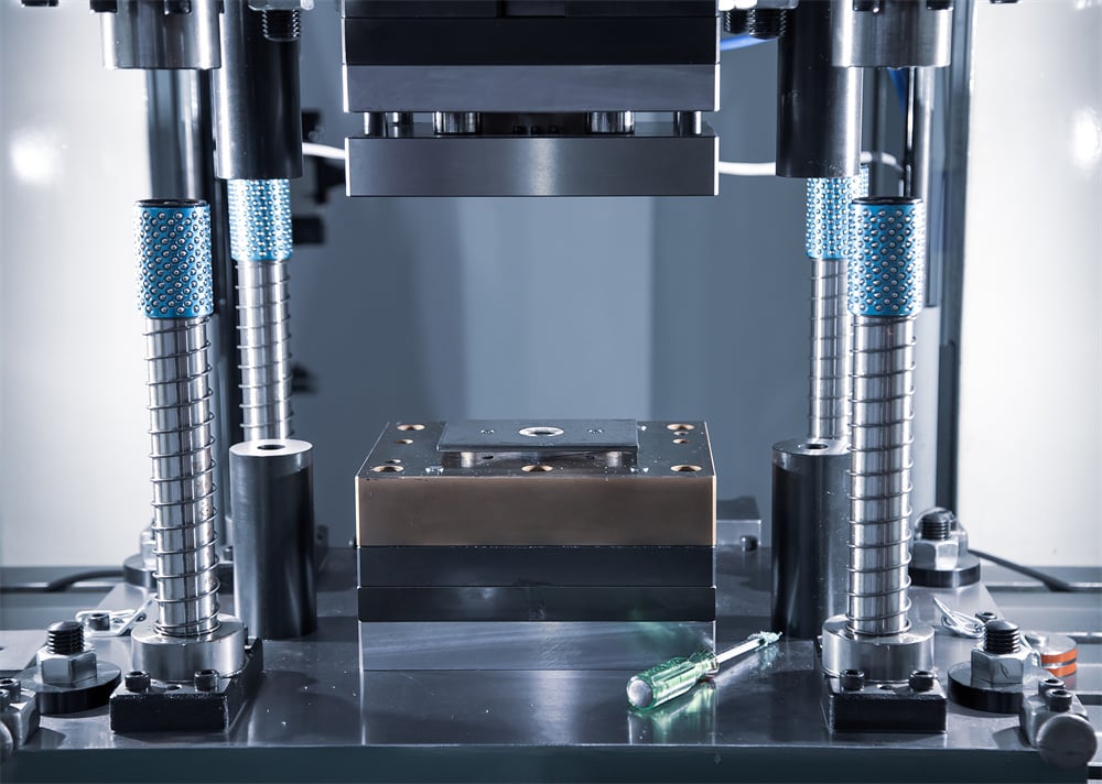
| Four-Column Press | 100 – 5000 Tons | Deep Drawing, Molding, Forging | Superior die alignment and pressure distribution |
| Horizontal Press | 20 – 500 Tons | Straightening, Pipe Bending | Ideal for long workpieces and bars |
Choosing between these types depends heavily on the geometry of the parts and the required precision. For instance, while a C-frame press offers excellent accessibility, it is prone to “yawing” or frame deflection under maximum load. In contrast, a four-column press provides the most stable platform for high-precision molding where even a fraction of a millimeter of misalignment could result in a rejected part.
Common Engineering Mistakes in Hydraulic Press Operation
Even with a solid understanding of how a hydraulic press works: a practical technical manufacturers guide would be incomplete without addressing common pitfalls. One of the most frequent mistakes is Off-Center Loading. Hydraulic presses are designed to apply force vertically through the center of the ram. When a workpiece is placed off-center, it creates a side load on the cylinder and the ram guides. Over time, this leads to uneven seal wear, oil leaks, and potential scoring of the cylinder walls. Always ensure that the tooling is centered or use a press designed with heavy-duty gib-guiding to handle eccentric loads.
Another common error is Neglecting Oil Quality. Hydraulic fluid is the lifeblood of the machine. It doesn’t just transmit power; it also lubricates moving parts and dissipates heat. Many manufacturers fail to implement a regular oil analysis program. Contaminants like moisture, metal shavings, or dust can act as abrasives, destroying the precision-machined surfaces of the valves and pumps. Furthermore, operating the press with overheated oil reduces its viscosity, leading to internal leakage and a significant drop in efficiency.
Incorrect Pressure Settings also plague many production floors. Operators sometimes believe that “more is better” and crank the relief valve to its maximum setting. This not only wastes energy but also puts unnecessary stress on the hydraulic hoses and fittings, increasing the risk of a catastrophic failure. A well-engineered process should use the minimum pressure required to achieve a quality part, which extends the lifespan of the machine and reduces the heat generated by the system.
Lastly, many manufacturers ignore the Decompression Cycle. When a press is under high tonnage, the hydraulic fluid and the machine frame actually compress slightly, storing energy like a spring. If the ram is retracted instantly, this energy is released as a “hydraulic shock,” which sounds like a loud bang and sends vibrations through the entire system. This shock can crack welds and loosen hydraulic fittings. Modern HARSLE presses include a decompression valve that slowly releases the pressure before the ram moves, a feature that should always be utilized in high-tonnage applications.
Selection Checklist for Manufacturers
When purchasing a new hydraulic press, manufacturers should follow a rigorous selection process to ensure the machine meets both current and future production needs. Use the following checklist as a guide:
- Define the Maximum Tonnage: Calculate the force required for your thickest and strongest material, then add a 20% safety factor.
- Evaluate Frame Rigidity: For high-precision work, opt for a four-column or H-frame design to minimize deflection.
- Assess Stroke and Daylight: Ensure the machine can accommodate your largest dies and provides enough room for part removal.
- Check Speed Requirements: Does the machine offer fast approach and return speeds to meet your cycle time targets?
- Control System Compatibility: Does the PLC allow for integration with robots or other automation tools in your factory?
- Safety Features: Ensure the press is equipped with light curtains, dual-hand palm buttons, and emergency stop circuits that meet local safety standards (like CE or OSHA).
- Maintenance Accessibility: Check if filters, pumps, and valves are easily accessible for routine servicing.
- Manufacturer Reputation: Choose a provider like HARSLE that offers robust technical support and readily available spare parts.
By systematically checking these factors, manufacturers can avoid the costly mistake of buying a machine that is either underpowered for their needs or overly complex for their operators. A well-chosen hydraulic press is a 20-year investment, so taking the time to verify these technical details is essential for long-term profitability.
Frequently Asked Questions (FAQ)
1. How often should I change the hydraulic oil?
For most industrial environments, hydraulic oil should be changed every 2,000 to 4,000 hours of operation. However, it is better to rely on oil analysis. Testing the oil for oxidation and particle count can tell you exactly when a change is needed, potentially saving money on unnecessary oil purchases while protecting your machinery.
2. Why is my hydraulic press losing pressure?
Pressure loss is usually caused by internal or external leaks. Check for visible oil around hoses and seals. If no external leaks are found, the problem may be an internal bypass in the cylinder or a malfunctioning relief valve. Worn pump components can also lead to an inability to maintain peak pressure.
3. Can I use a hydraulic press for high-speed stamping?
While hydraulic presses are generally slower than mechanical presses, modern “high-speed” hydraulic models exist. However, for extremely high-volume, thin-gauge stamping (hundreds of strokes per minute), a mechanical press is usually more efficient. Hydraulic presses excel where stroke flexibility and constant force are more important than raw speed.
4. What is the difference between a gear pump and a piston pump in a press?
Gear pumps are simpler, cheaper, and more robust but are generally limited to lower pressures (up to 3,000 PSI). Piston pumps are more complex and expensive but can handle much higher pressures (up to 10,000 PSI) and are more efficient, making them the standard choice for high-tonnage industrial presses.
5. How do I prevent the hydraulic system from overheating?
Ensure the cooling system (either air-cooled or water-cooled) is functioning correctly and that the heat exchanger fins are clean. Additionally, check that the relief valves are not set too low, which causes the pump to work against the valve constantly, generating excessive heat. Using the correct oil viscosity for your ambient temperature is also crucial.
6. Is it possible to retrofit an old hydraulic press with modern controls?
Yes, retrofitting is a common way to extend the life of a sturdy old frame. You can replace manual valves with proportional solenoid valves and add a PLC with a touch-screen HMI. This allows for better pressure control, recipe storage for different dies, and improved safety features.


