Hydraulic Press Technical Guide: Working Principle, Key Components, and Applications

Technical Overview of Hydraulic Press Systems
The hydraulic press is a cornerstone of modern industrial manufacturing, utilizing the properties of fluid mechanics to exert massive amounts of force on a workpiece. At its core, the hydraulic press operates based on Pascal’s Principle, which states that pressure exerted anywhere in a confined incompressible fluid is transmitted equally in all directions throughout the fluid such that the pressure ratio remains the same. This allows a relatively small amount of force applied at one point to be multiplied into a significantly larger force at another point, making it indispensable for tasks such as forging, stamping, and deep drawing.
In a technical context, the hydraulic press is more than just a force multiplier; it is a sophisticated system of energy conversion. Electrical energy powers a motor, which drives a hydraulic pump. This pump converts mechanical energy into hydraulic energy by moving fluid through a series of valves and hoses. Finally, the hydraulic cylinder converts this fluid energy back into mechanical energy, resulting in the linear motion of the ram. Modern HARSLE hydraulic presses integrate advanced CNC controls and proportional valve technology to ensure that this force is not only powerful but also precise and repeatable.
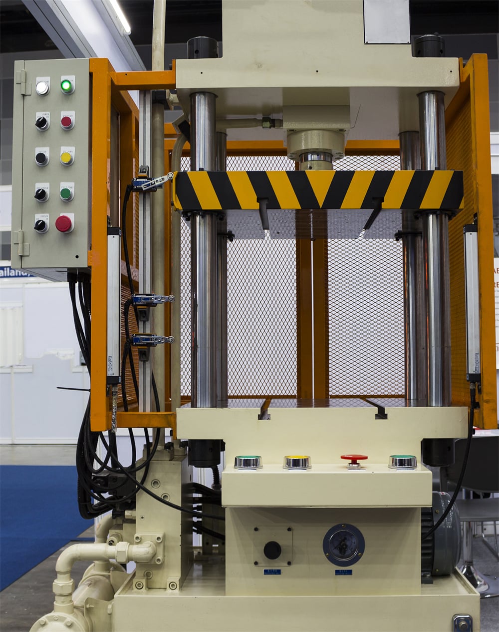
The evolution of hydraulic technology has led to the development of various frame designs, including the C-frame (gap frame), H-frame (four-column), and horizontal presses. Each design serves specific structural requirements. For instance, the four-column design provides exceptional rigidity and even distribution of pressure, which is critical for high-precision molding and heavy-duty forging. Conversely, the C-frame offers three-sided access, making it ideal for smaller components and manual loading operations. Understanding these structural nuances is the first step in mastering hydraulic press technology.
Furthermore, the efficiency of a hydraulic press is heavily dependent on the fluid used. Hydraulic oil serves multiple purposes: it transmits power, lubricates moving parts, and dissipates heat. The viscosity of the oil must be carefully selected based on the operating temperature and the speed of the press. High-performance systems often include filtration and cooling units to maintain oil integrity, as contamination is the leading cause of hydraulic system failure. By maintaining a clean and stable fluid environment, manufacturers can ensure the longevity and reliability of their machinery.
Core Parameters and Technical Specifications
When evaluating a hydraulic press, several core parameters define its capability and suitability for a specific application. The most prominent parameter is the Tonnage (Nominal Pressure). This represents the maximum force the press can exert. It is calculated based on the maximum pressure of the hydraulic system and the surface area of the main cylinder piston. Selecting the correct tonnage is vital; underestimating leads to incomplete forming, while overestimating can damage the tooling or the workpiece.
The Stroke Length is another critical specification. It defines the total distance the ram can travel from its fully retracted position to its fully extended position. For deep drawing applications, a long stroke is necessary to accommodate the depth of the part and the removal of the finished product. Along with stroke, the Daylight (Open Height)—the distance between the bolster plate and the ram in its fully up position—must be sufficient to house the dies and the workpiece.
Speed parameters are divided into three phases: Approach Speed, Pressing Speed, and Return Speed. The approach speed is the fast movement of the ram toward the work to minimize cycle time. The pressing speed is the slower, controlled movement during the actual forming process, where maximum force is applied. The return speed is the rapid retraction of the ram. Modern HARSLE machines utilize variable frequency drives and servo-hydraulic systems to optimize these speeds, significantly reducing energy consumption and improving cycle efficiency.
Finally, the Bolster Area and Ram Area dimensions determine the size of the dies that can be installed. These surfaces must be precision-ground to ensure parallelism. Any deviation in parallelism can lead to uneven wear on the guide rails and poor part quality. Technical specifications also include the motor power (kW), oil tank capacity, and the overall dimensions of the machine, which are essential for floor space planning and electrical infrastructure requirements.
Calculation Method for Hydraulic Force and Speed
To design or select a hydraulic press, engineers must perform precise calculations. The fundamental formula for force (F) in a hydraulic system is derived from Pascal’s Law: F = P × A, where ‘P’ is the pressure (typically in Bar or PSI) and ‘A’ is the effective area of the piston (typically in square centimeters or square inches).
For example, if a hydraulic system operates at a pressure of 250 Bar (approx. 3625 PSI) and the cylinder piston has a diameter of 200mm, the area (A) is calculated as π × (r²). In this case, r = 10cm, so A = 3.14159 × 100 = 314.16 cm². The force (F) would be 250 Bar × 314.16 cm² = 78,540 kg, or approximately 78.5 Tons. This calculation allows engineers to determine if a specific cylinder can meet the tonnage requirements of a project.
Speed calculations are equally important for production planning. The speed (v) of the ram is determined by the flow rate (Q) of the hydraulic pump and the area (A) of the cylinder: v = Q / A. If the pump delivers 100 liters per minute (L/min) and the cylinder area is 314.16 cm², the speed can be calculated by converting units appropriately. High-speed requirements necessitate larger pumps or the use of regenerative circuits, which redirect oil from the rod side of the cylinder back to the cap side during the approach stroke to increase velocity without requiring additional pump flow.
Another critical calculation involves the Dwell Time and Decompression. When the press reaches its target pressure, it may need to hold that pressure (dwell) to allow the material to set, particularly in composite molding or rubber vulcanization. Upon completion, the pressure must be released slowly (decompression) to prevent hydraulic shock, which can damage pipes and valves. Calculating the decompression time based on the volume of compressed oil is essential for maintaining the structural integrity of the hydraulic circuit.
Hydraulic Press Parameter Table
The following table provides a comparison of typical technical specifications for different types of hydraulic presses commonly used in metal fabrication.
| Parameter | 4-Column Press | C-Frame Press | H-Frame Press | Servo-Hydraulic Press |
|---|---|---|---|---|
| Tonnage Range | 100 – 5000 Tons | 10 – 250 Tons | 500 – 10000 Tons | 50 – 1000 Tons |
| Rigidity | High | Medium | Very High | High |
| Access | 4-Side Access | 3-Side Access | Front/Back Access | 4-Side Access |
| Typical Application | Deep Drawing, Molding | Punching, Assembly | Heavy Forging | Precision Forming |
| Speed Control | Standard/CNC | Manual/PLC | Advanced CNC | High-Precision Servo |
| Energy Efficiency | Standard | Standard | Medium | Very High |
Common Engineering Mistakes in Hydraulic Press Operation
One of the most frequent engineering mistakes is ignoring the effects of off-center loading. Hydraulic presses are designed to apply force along the vertical axis of the ram. When a die is placed off-center, it creates a moment arm that exerts side-loading forces on the ram and the guide bushings. Over time, this leads to premature wear, seal failure, and loss of parallelism. Engineers should always strive to center the load or use a press designed with heavy-duty guiding systems to counteract these forces.
Another common error is improper fluid maintenance. Many operators treat hydraulic oil as a “set and forget” component. However, hydraulic systems are extremely sensitive to particulate contamination and moisture. Even microscopic particles can act as abrasives, scoring the cylinder walls and damaging sensitive proportional valves. Regular oil analysis, filter changes, and maintaining the correct operating temperature are non-negotiable for industrial-grade machinery. Overheating oil reduces its viscosity, leading to internal leakage and a significant drop in volumetric efficiency.
Incorrect Tonnage Selection also plagues many fabrication shops. Using a 500-ton press for a job that only requires 50 tons might seem harmless, but it results in excessive energy consumption and unnecessary wear on the large-scale components. Conversely, running a press at its absolute maximum capacity for extended periods can lead to structural fatigue. The “sweet spot” for hydraulic press operation is typically between 60% and 80% of its rated capacity, which balances performance with machine longevity.
Finally, neglecting the decompression cycle can lead to catastrophic pipe bursts or valve failures. When oil is under high pressure, it actually compresses slightly (about 0.5% per 1000 PSI). If the directional valve is shifted instantly to the return position, this stored energy is released as a shockwave. Incorporating a decompression stage in the PLC logic allows the pressure to bleed off safely before the ram moves, protecting the entire hydraulic circuit from fatigue and sudden failure.
Selection Checklist for Industrial Hydraulic Presses
Choosing the right hydraulic press requires a systematic approach to ensure the machine meets both current and future production needs. Use the following checklist during your evaluation process:
- Define the Application: Are you performing deep drawing, blanking, forging, or assembly? The application dictates the frame style and speed requirements.
- Calculate Required Tonnage: Use material thickness, tensile strength, and bend length to determine the maximum force needed. Add a 20% safety margin.
- Determine Bed Size and Stroke: Ensure the bolster area can accommodate your largest dies and that the stroke is long enough for part removal.
- Evaluate Speed Requirements: If high-volume production is the goal, look for presses with fast approach and return speeds, or consider a servo-hydraulic model.
- Check Precision Standards: For high-tolerance work, verify the ram parallelism and the quality of the guiding system (e.g., 8-point gib guiding).
- Assess Control Systems: Does the machine require simple manual controls, or a full CNC interface with data logging and remote diagnostics?
- Safety Compliance: Ensure the press includes light curtains, dual-hand start buttons, and safety interlocks that meet local industrial standards (CE, OSHA, etc.).
- Maintenance and Support: Consider the availability of spare parts and the manufacturer’s reputation for technical support. HARSLE provides comprehensive after-sales service for all hydraulic systems.
Frequently Asked Questions (FAQ)
1. What is the difference between a hydraulic press and a mechanical press?
A hydraulic press uses fluid pressure to move the ram, providing full tonnage throughout the entire stroke. A mechanical press uses a flywheel and crankshaft, delivering maximum force only at the bottom of the stroke. Hydraulic presses are generally more versatile and easier to set up, while mechanical presses are faster for high-volume blanking.
2. How often should I change the hydraulic oil?
For most industrial applications, hydraulic oil should be changed every 2,000 to 4,000 hours of operation. However, it is better to rely on regular oil analysis to check for oxidation, water content, and particulate levels. If the oil appears cloudy or smells burnt, it should be replaced immediately.
3. Why is my hydraulic press losing pressure?
Pressure loss is usually caused by internal or external leaks. Check for visible leaks around seals and hose connections. If no external leaks are found, the issue may be internal, such as a worn piston seal in the cylinder or a malfunctioning pressure relief valve that is bypassing oil back to the tank.
4. Can I use a hydraulic press for high-speed stamping?
While traditional hydraulic presses are slower than mechanical ones, modern high-speed hydraulic presses equipped with accumulators and advanced valve blocks can achieve impressive cycle rates. For extremely high-speed stamping, a dedicated high-speed press or a servo-hydraulic press is recommended.
5. What are the benefits of a servo-hydraulic system?
Servo-hydraulic systems use a servo motor to drive the pump, allowing for precise control of flow and pressure. This results in up to 70% energy savings, reduced noise, less heat generation, and much higher precision in ram positioning compared to traditional fixed-displacement pump systems.
6. How do I ensure the safety of the operator?
Safety is paramount. Always use light curtains to prevent the press from operating if a hand enters the work area. Implement two-hand control stations, emergency stop buttons, and mechanical safety blocks for use during die changes. Regular safety inspections and operator training are also essential components of a safe workplace.


