Hydraulic Press Applications in Metalworking: Bending, Punching, and Deep Drawing

Technical Overview of Hydraulic Press Applications in Metalworking
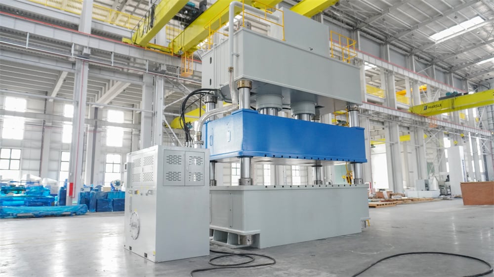
The hydraulic press remains a cornerstone of modern industrial manufacturing, particularly within the realm of metal fabrication. Utilizing the principles of Pascal’s Law, these machines generate immense force through fluid pressure, allowing for the precise manipulation of various metals. In the context of HARSLE’s advanced machinery, the hydraulic press is not merely a tool of brute force but a sophisticated system capable of high-precision tasks such as bending, punching, and deep drawing. These three applications represent the majority of sheet metal forming operations globally, each requiring specific configurations of pressure, speed, and control.
Bending involves the deformation of a metal sheet along a straight axis to create V-shapes, U-shapes, or channel shapes. Unlike mechanical presses, hydraulic presses offer full tonnage throughout the entire stroke, which is critical for maintaining consistent angles in thick materials. Punching, on the other hand, is a subtractive process where a tool and die set are used to create holes or cutouts. The hydraulic system’s ability to control the descent speed helps in reducing the shock to the tooling, thereby extending the life of the punches. Deep drawing is perhaps the most complex of the three, involving the radial drawing of a metal blank into a forming die by the mechanical action of a punch. It is a process that transforms flat sheets into hollow, cup-shaped parts, such as kitchen sinks or automotive fuel tanks.
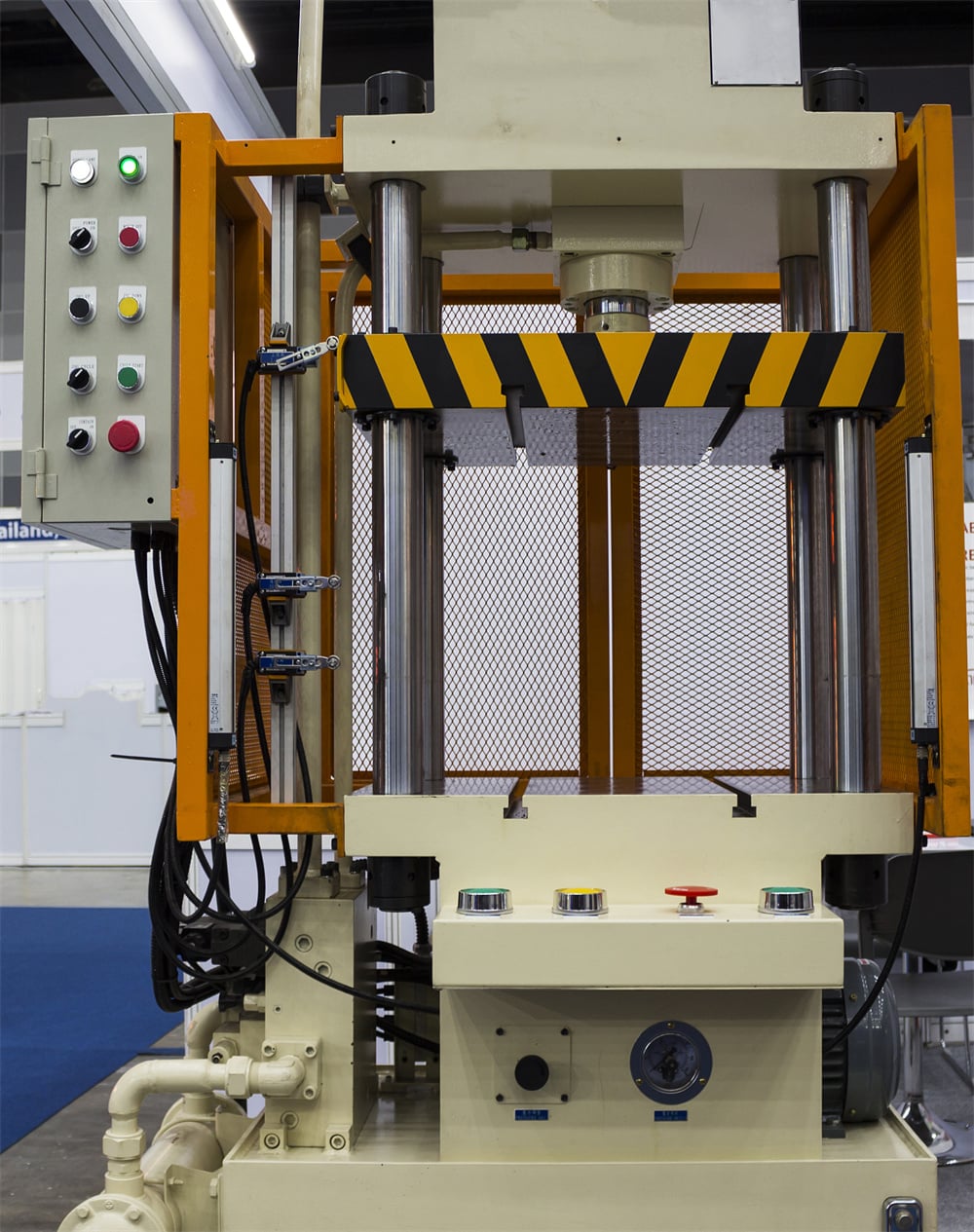
The versatility of hydraulic presses in these applications stems from their controllable stroke length and adjustable pressure. Modern HARSLE hydraulic presses are equipped with CNC systems that allow operators to program specific profiles for the ram’s movement. This level of control is essential for materials with high springback or those that require a slow, steady draw to prevent tearing. Furthermore, the integration of safety features like light curtains and dual-hand controls ensures that these high-force operations are conducted with minimal risk to the operator.
Understanding the nuances of these applications requires a deep dive into the physics of metal deformation. When a metal is bent or drawn, it undergoes elastic and then plastic deformation. The hydraulic press must provide enough force to overcome the material’s yield strength while remaining within the limits of its ultimate tensile strength to avoid fracture. By fine-tuning the hydraulic flow and pressure, manufacturers can achieve repeatable results across thousands of cycles, making the hydraulic press an indispensable asset in mass production environments.
Core Parameters for Metalworking Operations
To achieve optimal results in bending, punching, and deep drawing, several core parameters must be meticulously managed. The first and most obvious is Tonnage (Force). This is the maximum pressure the press can exert. For punching, tonnage is calculated based on the perimeter of the hole and the shear strength of the material. For bending, it depends on the material thickness and the V-opening of the die. In deep drawing, the tonnage must be sufficient to overcome the resistance of the metal being pulled into the die cavity while also providing enough blank holder force to prevent wrinkling.
Stroke Length and Speed are equally vital. The stroke length determines how deep the press can reach, which is particularly important for deep drawing applications where the part height might be significant. Speed is often divided into three phases: approach speed, pressing speed, and return speed. A fast approach saves time, while a controlled pressing speed is necessary to ensure the metal flows correctly without cracking. HARSLE presses often feature variable speed controls to optimize these cycles for different material types, such as aluminum, stainless steel, or carbon steel.
Daylight and Bolster Size define the physical workspace of the machine. Daylight is the vertical distance between the bed and the ram when it is in the fully open position. This must be large enough to accommodate the tooling and the finished part. The bolster size refers to the dimensions of the work table. A larger bolster allows for the installation of multi-stage dies or larger workpieces. In punching operations, the bolster must also be rigid enough to withstand the concentrated shock loads without deflecting, as deflection can lead to tool misalignment and premature wear.
Finally, Blank Holder Force (BHF) is a parameter specific to deep drawing. This is the pressure applied to the edges of the metal blank to control its flow into the die. If the BHF is too low, the material will wrinkle; if it is too high, the material will thin excessively or tear. Advanced hydraulic presses use a separate hydraulic cushion or a secondary cylinder to provide a constant or programmable BHF throughout the drawing cycle, ensuring a high-quality finish and structural integrity of the part.
Calculation Methods for Press Operations
Accurate calculations are the foundation of successful metalworking. For Punching, the required tonnage (P) can be calculated using the formula: P = L × t × τ, where ‘L’ is the total length of the cut (perimeter), ‘t’ is the material thickness, and ‘τ’ is the shear strength of the material. It is common practice to add a 15-20% safety margin to this figure to account for tool dulling and material variations. For example, punching a 50mm diameter hole in 3mm thick mild steel with a shear strength of 345 MPa would require approximately 16.5 tons of force.
For Bending, the formula for V-bending force is: P = (C × S × L × t²) / W. Here, ‘C’ is a constant (usually 1.33 for air bending), ‘S’ is the tensile strength, ‘L’ is the length of the bend, ‘t’ is the thickness, and ‘W’ is the width of the V-die opening. Choosing the correct V-opening is crucial; typically, W is 8 times the material thickness for materials up to 6mm. Incorrectly calculating the bending force can lead to machine overload or inaccurate bend angles due to excessive frame deflection.
Deep Drawing calculations are more complex because they involve the Draw Ratio (DR). The DR is the ratio of the blank diameter (D) to the punch diameter (d). A standard limit for a single draw is a DR of 2.0. The force required for deep drawing is calculated as: P = π × d × t × S × [(D/d) – 0.7]. Additionally, the blank holder force is usually estimated at about 33% of the total drawing force. These calculations help engineers determine if a part can be made in a single operation or if multiple “redrawing” steps are necessary to reach the final depth without compromising the material’s thickness.
Parameter Table for Common Materials
| Material Type | Thickness (mm) | Punching Force (kN/mm) | Bending Force (kN/m, V=8t) | Deep Draw Ratio (Max) |
|---|---|---|---|---|
| Mild Steel (CR4) | 1.0 | 0.35 | 70 | 2.1 |
| Mild Steel (CR4) | 2.0 | 0.70 | 140 | 2.0 |
| Stainless Steel (304) | 1.0 | 0.55 | 110 | 1.9 |
| Stainless Steel (304) | 2.0 | 1.10 | 220 | 1.8 |
| Aluminum (5052) | 1.0 | 0.20 | 40 | 2.2 |
| Aluminum (5052) | 2.0 | 0.40 | 80 | 2.1 |
Note: The values provided in the table are estimates for general guidance. Actual requirements may vary based on specific material grades, heat treatment, and tooling conditions. Always consult with HARSLE technical support for precise machine sizing.
Common Engineering Mistakes in Hydraulic Pressing
One of the most frequent mistakes in hydraulic press operations is Incorrect Tonnage Estimation. Many operators rely on guesswork or outdated charts, leading to either machine strain or poor part quality. Underestimating the force required for punching can result in the press stalling or the punch getting stuck in the material. Conversely, using excessive force for bending can cause “coining,” where the material is crushed rather than bent, leading to unpredictable springback and potential damage to the die.
Another critical error is Neglecting Tool Alignment. In punching and deep drawing, the clearance between the punch and the die is often measured in microns. Even a slight misalignment can cause uneven wear, burrs on the workpiece, or catastrophic tool failure. This is often caused by uneven loading on the press bed or failing to secure the bolster plate properly. Regular inspection of the ram guides and the use of precision-ground tool holders are essential to mitigate this risk.
Inadequate Lubrication is a silent killer of productivity, especially in deep drawing. As the metal is pulled into the die, it generates significant friction and heat. Without the correct lubricant, the metal can “gall” or weld itself to the die surface, resulting in torn parts and ruined tooling. Engineers must select lubricants based on the material type—for instance, heavy oils for stainless steel or synthetic esters for aluminum. Furthermore, the application method (spraying, rolling, or dipping) must ensure even coverage across the entire blank.
Finally, Ignoring Material Grain Direction can lead to unexpected cracking during bending. Most sheet metals have a grain direction resulting from the rolling process at the mill. Bending parallel to the grain is much more likely to cause fractures than bending perpendicular to it. When nesting parts for a production run, engineers must account for this orientation to ensure structural integrity, particularly in high-stress components used in the aerospace or automotive industries.
Selection Checklist for a Hydraulic Press
- Define the Primary Application: Will the machine be used mostly for deep drawing (requiring a cushion), punching (requiring high-speed shock absorption), or bending?
- Calculate Maximum Tonnage: Determine the highest force required for your thickest and strongest material, then add a 20% safety buffer.
- Evaluate Stroke and Daylight: Ensure the press has enough vertical travel for your deepest parts and enough open space for easy tool changes.
- Check Bed Rigidity: For punching applications, look for a press with a heavy-duty frame to minimize deflection and vibration.
- Assess Control Systems: Does the machine offer CNC integration, programmable pressure profiles, and digital readouts for precision?
- Consider Speed Requirements: If high-volume production is the goal, look for machines with fast approach and return speeds.
- Safety Compliance: Ensure the machine meets local safety standards (CE, OSHA) and includes features like light curtains and emergency stops.
- Maintenance and Support: Choose a reputable manufacturer like HARSLE that provides comprehensive manuals, spare parts availability, and technical support.
Frequently Asked Questions (FAQ)
1. What is the main advantage of a hydraulic press over a mechanical press?
The primary advantage is flexibility. A hydraulic press provides full tonnage at any point in the stroke, allows for adjustable stroke lengths, and offers precise control over pressing speed. This makes it far superior for deep drawing and complex bending compared to the fixed-stroke nature of mechanical presses.
2. How do I prevent wrinkling in deep drawing?
Wrinkling is usually caused by insufficient blank holder force. By increasing the pressure on the blank holder, you can control the flow of the material into the die. However, you must balance this to avoid thinning or tearing the material. Using a hydraulic cushion can provide the necessary consistent pressure.
3. Can I use a hydraulic press for high-speed punching?
While hydraulic presses are generally slower than mechanical turret punches, modern high-speed hydraulic presses from HARSLE are designed with advanced valves and accumulators that allow for rapid cycling. They are excellent for heavy-duty punching where force is more critical than extreme speed.
4. What maintenance does a hydraulic press require?
Regular maintenance includes checking hydraulic fluid levels and quality, inspecting seals for leaks, lubricating the ram guides, and ensuring the cooling system is functioning. It is also vital to check the calibration of pressure gauges and CNC sensors annually to maintain accuracy.
5. Why is my bend angle inconsistent?
Inconsistent angles are often due to material springback or machine deflection. Ensure you are using the correct tonnage and that your V-die is appropriate for the material thickness. If the problem persists, you may need to implement a “dwell time” at the bottom of the stroke to allow the material to set, or adjust your CNC program to over-bend slightly to compensate for springback.


