Comprehensive Guide: How to Maintain Stable Pressure in a Hydraulic Press System for Peak Performance

Technical Overview of Pressure Stability in Hydraulic Systems
In the realm of metal fabrication, the ability to maintain stable pressure in a hydraulic press system is not merely a matter of operational preference; it is a fundamental requirement for precision, repeatability, and structural integrity of the finished product. A hydraulic press operates on Pascal’s Principle, which states that pressure applied to a confined fluid is transmitted undiminished in every direction. However, in a real-world industrial environment, various factors such as thermal expansion, fluid compressibility, and mechanical wear can introduce fluctuations that compromise the stability of this pressure.
To maintain stable pressure in a hydraulic press system, one must understand the dynamic relationship between the hydraulic pump, the control valves, and the actuator (the cylinder). The system must be designed to compensate for internal leakage and external load variations. HARSLE hydraulic presses are engineered with high-precision components to minimize these variables, but consistent maintenance and a deep understanding of the system’s physics are required to keep the machine performing at its peak. Pressure instability often manifests as ‘chatter’ in the workpiece, inconsistent thickness in deep-drawn parts, or even catastrophic failure of the hydraulic seals.
The stability of pressure is also heavily dependent on the quality of the hydraulic medium. Hydraulic oil is not just a lubricant; it is the power transmission fluid. If the oil contains dissolved air or moisture, its bulk modulus (resistance to compression) decreases significantly. This leads to a ‘spongy’ system where pressure takes longer to build and fluctuates wildly under load. Therefore, maintaining stable pressure starts with the fluid itself—ensuring it is clean, de-aerated, and kept within an optimal temperature range.
Modern hydraulic systems often employ closed-loop control mechanisms. These systems use pressure transducers to provide real-time feedback to a Programmable Logic Controller (PLC). The PLC then adjusts the proportional valves or the variable displacement pump to counteract any deviations from the set point. This level of automation is standard in HARSLE’s advanced series, allowing operators to achieve tolerances that were previously impossible with manual or open-loop systems.
Core Parameters Influencing Pressure Stability
Several critical parameters dictate how effectively a system can maintain stable pressure in a hydraulic press system. Understanding these variables allows engineers and operators to diagnose issues before they lead to downtime. The first and perhaps most significant parameter is Fluid Viscosity. Viscosity is the measure of a fluid’s resistance to flow. If the viscosity is too low (often due to high temperatures), internal leakage across pump vanes and valve spools increases, making it difficult to hold pressure. Conversely, if viscosity is too high, the pump may cavitate, leading to pressure spikes and mechanical damage.
Another core parameter is the Response Time of Control Valves. In high-speed stamping or forging operations, the system must react to load changes in milliseconds. Proportional and servo valves are designed for this purpose. Their ability to modulate flow precisely determines how well the system can dampen pressure surges. If a valve is sluggish due to contamination or wear, the pressure will ‘overshoot’ the target and then ‘hunt’ for the correct level, creating instability.
- System Rigidity: The mechanical stiffness of the press frame and the hydraulic piping. Flexible hoses can expand under pressure, acting like a spring and absorbing energy that should be directed at the workpiece.
- Pump Efficiency: The volumetric efficiency of the pump determines its ability to provide a constant flow rate against high backpressure.
- Accumulator Pre-charge: Hydraulic accumulators store energy in the form of compressed gas. If the nitrogen pre-charge is incorrect, the accumulator cannot effectively smooth out pressure pulsations from the pump.
- Filtration Micron Rating: Contaminants as small as 5-10 microns can score valve seats, leading to ‘weeping’ or internal bypass, which is a primary cause of pressure drop.
Temperature control is the silent guardian of pressure stability. As hydraulic oil heats up, its molecules move faster and the fluid becomes thinner. Most industrial hydraulic systems are designed to operate between 40°C and 55°C. Exceeding this range leads to rapid oxidation of the oil and degradation of synthetic seals. HARSLE incorporates robust cooling systems, either air-cooled or water-cooled, to ensure that the thermal equilibrium is maintained even during 24/7 production cycles.
Calculation Method for Pressure and Force
To maintain stable pressure in a hydraulic press system, engineers must first accurately calculate the required parameters for the specific application. The most basic calculation is the relationship between pressure, force, and area. This is expressed by the formula: F = P × A, where F is the force (Newtons or Tons), P is the pressure (Pascals or PSI), and A is the effective area of the piston (square meters or square inches).
However, for stability, we must also consider the Pressure Drop (ΔP) across the system. The pressure drop through a pipe or valve can be estimated using a simplified version of the Darcy-Weisbach equation. For hydraulic systems, we often look at the flow coefficient (Cv) of valves. The formula Q = Cv × √(ΔP/SG) (where Q is flow rate and SG is specific gravity) helps in selecting valves that won’t cause excessive pressure loss, which would otherwise lead to instability at high flow rates.
Another vital calculation involves Accumulator Sizing. If an accumulator is used to maintain pressure during a dwell cycle or to dampen shocks, its volume must be calculated based on the gas laws (Boyle’s Law: P1V1 = P2V2). For example, if you need to maintain a pressure of 200 bar and the system experiences a momentary demand of 2 liters of oil, the accumulator must be sized such that the expansion of the nitrogen bladder doesn’t drop the pressure below the minimum required threshold. Proper sizing ensures that the ‘buffer’ provided by the accumulator is sufficient to keep the system stable during peak demands.
Technical Parameter Table for Hydraulic Press Operations
The following table provides a general guideline for the parameters required to maintain stable pressure across different types of hydraulic press applications. Note that these are typical values and may vary based on specific HARSLE model configurations.
| Application Type | Typical Pressure Range (Bar) | Required Stability Tolerance | Recommended Oil Viscosity (ISO VG) | Cooling Method |
|---|---|---|---|---|
| Precision Stamping | 150 – 250 | ±1.5% | 46 | Air/Oil Heat Exchanger |
| Deep Drawing | 200 – 350 | ±1.0% | 68 | Water-Cooled Chiller |
| Heavy Forging | 300 – 500 | ±2.0% | 68 or 100 | High-Capacity Water |
| Powder Compaction | 100 – 400 | ±0.5% | 32 or 46 | Closed-Loop Refrigeration |
| General Assembly | 50 – 150 | ±5.0% | 46 | Passive/Ambient |
Maintaining these parameters requires a combination of high-quality hardware and diligent monitoring. For instance, in powder compaction, where the tolerance is a strict ±0.5%, the use of high-response servo-proportional valves is mandatory. In contrast, general assembly tasks can tolerate wider fluctuations, allowing for more cost-effective fixed-displacement pump systems.
Common Engineering Mistakes in Pressure Maintenance
One of the most frequent mistakes made by maintenance teams is ignoring air entrainment. Air is highly compressible. When air bubbles are trapped in hydraulic fluid, they compress under load, causing the cylinder to move erratically and the pressure to fluctuate. This is often caused by a low oil level in the reservoir, a leaky suction line, or failing pump shaft seals. To maintain stable pressure in a hydraulic press system, the system must be properly bled, and the reservoir should be designed with baffles to allow air to escape before the oil is recirculated.
Another common error is the improper setting of relief valves. Some operators set the main relief valve too close to the working pressure. This causes the valve to ‘crack’ or partially open during normal operation, leading to pressure dithering and excessive heat generation. The relief valve should typically be set 10-15% above the maximum working pressure to ensure it only opens during a genuine overpressure event. Furthermore, using the wrong type of hydraulic hose—one with too much volumetric expansion—can lead to a loss of ‘stiffness’ in the hydraulic circuit, making pressure control difficult.
Neglecting thermal management is a recipe for instability. As discussed, heat thins the oil. If a system is designed for a specific viscosity and the oil temperature climbs from 40°C to 70°C, the internal leakage in the pump can increase by as much as 50%. This makes it impossible for the pump to maintain the set pressure under load. Many engineers fail to account for the ‘duty cycle’ of the machine; a press that stays stable for one hour might fail after four hours of continuous operation if the cooling system is undersized.
Finally, contamination control is often overlooked. Even microscopic particles can wedge themselves between a valve spool and its housing. This prevents the valve from closing fully or moving smoothly, leading to ‘pressure drifting.’ A robust filtration strategy, including high-quality return line filters and off-line ‘kidney loop’ filtration, is essential for long-term pressure stability. HARSLE recommends regular oil analysis to monitor the ISO cleanliness code of the hydraulic fluid.
Selection Checklist for a High-Stability Hydraulic Press
When purchasing a new machine or upgrading an existing one, use this checklist to ensure the equipment is capable of maintaining stable pressure under your specific production requirements:
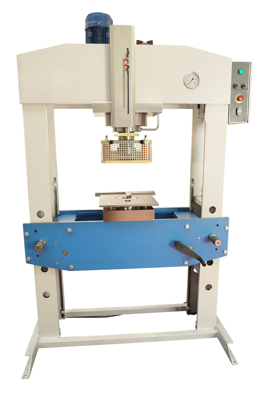
- Frame Deflection Rating: Does the press have a heavy-duty H-frame or C-frame with minimal deflection? A rigid frame prevents mechanical ‘spring-back’ that can affect pressure readings.
- Pump Type: Is it a variable displacement piston pump? These are superior for pressure stability compared to gear pumps as they can adjust flow to maintain a constant pressure.
- Control Logic: Does the PLC support PID (Proportional-Integral-Derivative) control for the hydraulic circuit? This is critical for fine-tuning pressure response.
- Transducer Quality: Are the pressure sensors high-accuracy (0.1% to 0.25% full scale)? Cheap sensors provide noisy data to the controller.
- Sealing Technology: Does the cylinder use low-friction, high-pressure seals (like PTFE-based seals) to prevent ‘stick-slip’ motion?
- Cooling Capacity: Is the heat exchanger rated for the maximum ambient temperature of your facility and the 100% duty cycle of the press?
- Accumulator Inclusion: For applications requiring rapid pressure build-up or long dwell times, is a properly sized accumulator included in the circuit?
Frequently Asked Questions (FAQ)
Why does my hydraulic press lose pressure during a long dwell cycle?
Pressure loss during a dwell cycle is usually caused by internal leakage. This can occur across the piston seals in the cylinder or through the directional control valve. If the pump is turned off during the dwell, the system relies on the integrity of the check valves and seals. To maintain stable pressure in a hydraulic press system during long dwells, a ‘pressure-compensated’ pump or a small ‘jockey pump’ is often used to make up for these minor internal leaks.
How does air in the hydraulic oil affect pressure stability?
Air is approximately 10,000 times more compressible than hydraulic oil. When air is present, the system loses its ‘stiffness.’ This results in a delay in pressure build-up, erratic movement of the ram, and fluctuations in the pressure gauge readings. It can also cause ‘dieseling,’ where air bubbles explode under high pressure, damaging seals and pitting metal surfaces.
What is the best way to monitor pressure stability?
The best way is to use a digital data logger connected to the system’s pressure transducers. This allows you to see a graph of pressure over time. If you see a ‘sawtooth’ pattern, it usually indicates a hunting control valve or a failing accumulator. A steady, flat line indicates a stable system. HARSLE’s modern control interfaces often include built-in graphing tools for this purpose.
Can I use any hydraulic oil in my HARSLE press?
No. You must use oil that meets the ISO viscosity grade and additive requirements specified in the manual. Using oil with the wrong viscosity will directly impact the system’s ability to maintain stable pressure. High-quality anti-wear (AW) hydraulic oils are generally recommended to protect the precision components that regulate pressure.
How often should I calibrate the pressure sensors?
For high-precision applications, pressure sensors should be calibrated at least once a year. Over time, electronic sensors can ‘drift,’ meaning they report a pressure that is slightly different from the actual physical pressure in the line. Regular calibration ensures that the PLC is making decisions based on accurate data.
What role does the manifold play in pressure stability?
The hydraulic manifold acts as the ‘nerve center’ of the system. A well-designed manifold minimizes the distance between valves and the cylinder, reducing the volume of oil that can compress and the number of potential leak points (fittings). HARSLE uses integrated manifolds to reduce vibration and ensure a more stable flow path for the hydraulic fluid.


