Press Brake Electrical Troubleshooting: Sensors, Switches, and Wiring Faults


Introduction to Press Brake Electrical Systems
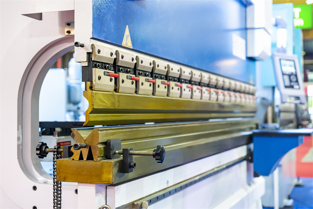
In the modern metal fabrication industry, the CNC press brake is a marvel of integration between heavy-duty hydraulics and sophisticated electronic control. While the mechanical frame and hydraulic cylinders provide the raw force necessary to bend thick steel plates, the electrical system acts as the brain and nervous system of the machine. When a press brake fails to cycle, loses its positioning accuracy, or throws a cryptic error code on the controller, the culprit is frequently found within the electrical circuit—specifically involving sensors, switches, or the intricate web of wiring that connects them.
Effective Press Brake Electrical Troubleshooting: Sensors, Switches, Wiring Faults requires a systematic approach. Unlike mechanical wear, which is often visible to the naked eye, electrical faults can be intermittent and elusive. A loose wire might only lose contact when the machine vibrates during a high-tonnage bend, or a proximity sensor might fail only when the ambient temperature in the shop rises. For operators and maintenance technicians, understanding how these components interact is the first step toward reducing downtime and maintaining the high precision that HARSLE machines are known for.
This comprehensive guide delves into the technical nuances of diagnosing electrical issues. We will explore the common failure points in modern press brakes, from the safety light curtains to the backgauge limit switches, and provide actionable advice on how to isolate and rectify these problems. By the end of this article, you will have a deeper understanding of the electrical architecture of your machinery and the tools required to keep it running at peak performance.
Key Considerations Before Troubleshooting
Before opening the electrical cabinet or probing a sensor with a multimeter, safety must be the absolute priority. Press brakes operate under immense hydraulic pressure and utilize high-voltage electricity (often 220V, 380V, or 480V AC). Always follow Lockout/Tagout (LOTO) procedures to ensure the machine cannot be accidentally energized while you are working on the internal components. Even when the main power is off, capacitors in the motor drives may hold a residual charge, so allow sufficient time for discharge.
Another critical consideration is the environment of the metal fabrication shop. Dust, oil mist, and metal shavings are the enemies of electrical components. Conductive dust can bridge terminals in a junction box, leading to short circuits, while oil can degrade the insulation on wiring over time. When troubleshooting, always inspect the physical condition of the components for signs of contamination or overheating. A burnt smell or discolored wire insulation is often a more direct clue than any software error message.
Finally, always have the machine’s electrical schematics and manual at hand. HARSLE provides detailed wiring diagrams for all CNC models. These schematics are the roadmap of the machine; they tell you which PLC input corresponds to which sensor and how the safety circuit is looped. Without a schematic, troubleshooting becomes a game of guesswork that can lead to further damage or safety risks. Ensure you understand the difference between the control circuit (typically 24V DC) and the power circuit (high-voltage AC) before beginning your diagnosis.
Technical Details: Sensors and Their Failure Modes
Proximity Sensors and Encoders
Proximity sensors are the “eyes” of the press brake, detecting the position of the ram and the backgauge fingers. Most modern machines use inductive proximity sensors to signal the end of travel or the reference point (home position). If a sensor fails, the CNC controller may not know where the ram is, preventing the machine from initiating a stroke. Common issues include the sensor being knocked out of alignment by a workpiece or the accumulation of metal dust on the sensor face, which can cause a “false positive” signal.
Linear encoders and rotary encoders are even more critical for precision. These devices provide real-time feedback on the position of the Y1 and Y2 axes. If an encoder cable is damaged or if the glass scale inside a linear encoder becomes dirty, the machine will lose its synchronization. This often manifests as an “Angle Deviation” error or the ram descending unevenly. Troubleshooting encoders involves checking the signal integrity with an oscilloscope or, more commonly, checking for physical obstructions and ensuring the reading head is properly gapped.
Laser Safety Systems and Light Curtains
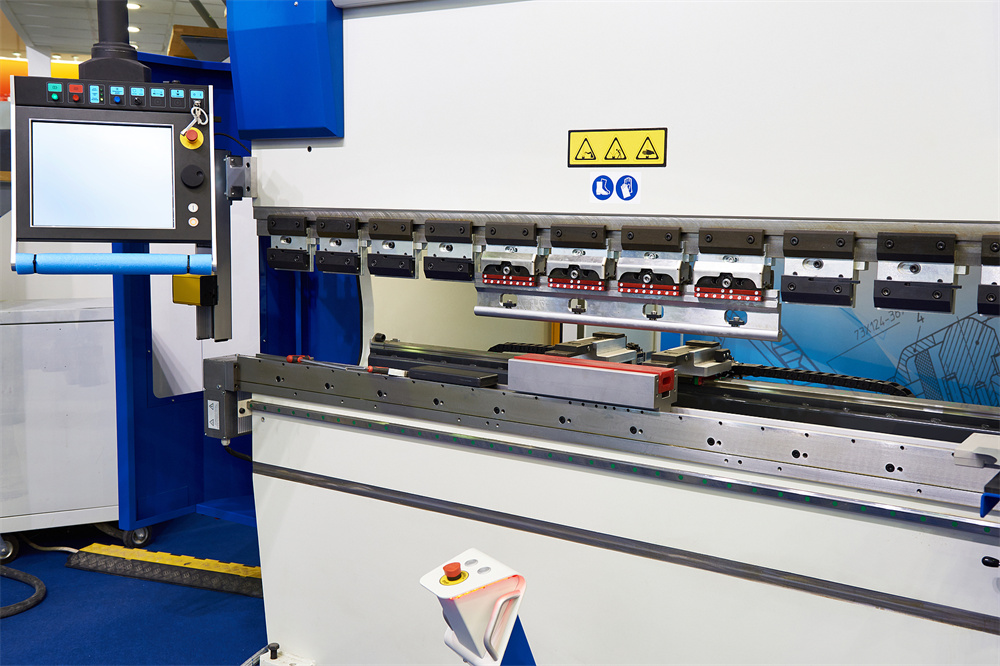
Safety is paramount in press brake operation. Systems like the DSP or Fiessler laser guards are integrated into the electrical stop circuit. These sensors project a laser beam just below the punch tip. If the beam is interrupted during the high-speed descent, the electrical system immediately cuts power to the hydraulic valves. Troubleshooting these often involves checking for alignment. If the transmitter and receiver are even a few millimeters out of sync due to machine vibration, the press brake will refuse to move. Cleaning the optical lenses is the most common maintenance task for these sensors.
Technical Details: Switches and Control Logic
The Foot Switch and Emergency Stops
The foot pedal is perhaps the most frequently used electrical component on a press brake. Because it sits on the floor, it is subject to physical impact, moisture, and heavy use. Internally, the foot switch contains multiple micro-switches for the “down” and “up” commands, as well as an emergency stop. A common fault is a broken spring or a frayed cable at the entry point of the pedal housing. If the machine only moves in one direction or fails to respond to the pedal entirely, the foot switch is the first place to look.
Emergency stop (E-stop) buttons are wired in a normally closed (NC) series circuit. This means that if any button in the chain is pressed—or if a wire in that chain breaks—the circuit opens and the machine stops. Troubleshooting an E-stop fault involves checking the continuity of the entire loop. Often, a mushroom button on the side of the machine has been bumped and slightly depressed, or a contact block has vibrated loose from the back of the button.
Limit Switches and Pressure Switches
Limit switches serve as the final mechanical-to-electrical safeguard to prevent the backgauge or ram from over-traveling and causing structural damage. These switches are often located in hard-to-reach areas. If a limit switch gets stuck in the “active” position due to grease buildup or a bent actuator arm, the CNC will prevent movement in that direction. Similarly, pressure switches monitor the hydraulic system. If the electrical contact in the pressure switch fails, the machine may not reach the required tonnage or may fail to transition from fast approach to slow pressing speed.
Technical Details: Wiring Faults and EMI
Loose Connections and Terminal Blocks
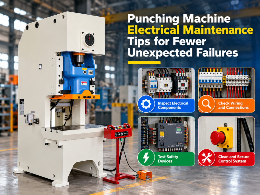
Vibration is a constant factor in metal fabrication. Over months and years of operation, the vibrations from the hydraulic pump and the impact of the bending process can loosen screw terminals in the electrical cabinet. A loose wire can cause intermittent faults that are notoriously difficult to track down. During a routine maintenance check, it is advisable to “tug-test” wires in the terminal blocks and ensure all connections are tight. Pay special attention to the ground (PE) wires, as a poor ground can cause erratic behavior in the CNC controller.
Cable Fatigue in Drag Chains
The backgauge of a CNC press brake moves constantly. The cables providing power and signal to the backgauge motors are housed in flexible plastic drag chains (caterpillar tracks). Over time, the repeated bending causes the copper strands inside the wires to fatigue and eventually break. This is a common cause of “Axis Following Error” or communication loss with the servo drives. When replacing these cables, it is vital to use high-flex cables designed for continuous motion rather than standard industrial wire.
Electromagnetic Interference (EMI)
Modern press brakes use Variable Frequency Drives (VFDs) and servo motors, which can generate significant electromagnetic noise. If signal wires (like those for encoders or sensors) are run too close to high-voltage power lines without proper shielding, EMI can corrupt the data. This leads to “ghost” errors or erratic positioning. Ensure that all shielded cables are properly grounded at one end and that signal and power cables are separated by the recommended distance within the wire ducts.
Selection Advice for Electrical Components
When it comes to replacing electrical components in a press brake, the temptation to use generic, low-cost alternatives can be high. However, in the context of Press Brake Electrical Troubleshooting: Sensors, Switches, Wiring Faults, quality is synonymous with reliability and safety. Here is how to select the right components:
- OEM Compatibility: Always prioritize original equipment manufacturer (OEM) parts. HARSLE machines are designed with specific component tolerances in mind. A sensor with a slightly different response time or voltage range can cause timing issues in the PLC logic.
- Industrial Grading: Ensure that replacement switches and sensors have an appropriate IP (Ingress Protection) rating. For a metal shop, IP65 or higher is recommended to protect against dust and oil splashes.
- Gold-Plated Contacts: For low-voltage signal circuits (like PLC inputs), switches with gold-plated contacts are preferred because they resist oxidation better than silver contacts, ensuring a reliable signal over millions of cycles.
- Shielded Cabling: When replacing wiring, always match the original specifications. If the original was a twisted-pair shielded cable, do not replace it with standard multi-core wire, as this will likely introduce EMI issues.
Common Troubleshooting Table
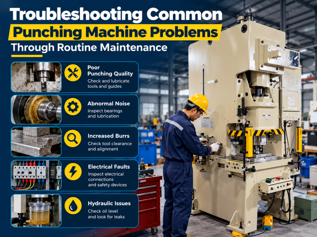
| Symptom | Possible Electrical Cause | Diagnostic Action |
|---|---|---|
| Ram will not descend | Safety light curtain interrupted or misaligned | Check alignment LEDs on the receiver; clean lenses. |
| Backgauge “Following Error” | Broken wire in the drag chain or faulty encoder | Check continuity of motor and encoder cables while moving the axis. |
| Machine won’t start (No Power) | E-stop engaged or blown control transformer fuse | Check all E-stop buttons and test fuses in the electrical cabinet. |
| Inaccurate bending depth | Linear encoder scale is dirty or loose | Clean the glass scale with alcohol and check mounting bolts. |
| Intermittent PLC errors | Loose terminal connections or EMI | Tighten all terminal screws and check cable shielding/grounding. |
FAQ: Press Brake Electrical Troubleshooting
1. Why does my press brake stop mid-stroke without an error message?
This is often caused by a momentary break in the safety circuit. Check the foot pedal cable for internal breaks and ensure the safety light curtains are not being triggered by a swinging workpiece or vibration. Also, check the hydraulic pressure switch; if it flickers, the PLC may pause the cycle.
2. How can I tell if a proximity sensor is bad?
Most proximity sensors have a small LED on the back. If the LED lights up when metal is near but the PLC doesn’t register the input, the sensor’s output transistor may be blown, or there is a break in the signal wire. Use a multimeter to check for 24V DC at the PLC input terminal when the sensor is triggered.
3. What causes a “Servo Drive Fault” on the CNC screen?
This can be caused by several factors: a mechanical jam causing an over-current, a loss of one phase of the incoming power, or a communication error between the CNC and the drive. Check the display on the actual servo drive inside the cabinet; it will usually show a specific hex code that points to the exact problem.
4. Can I bypass a faulty safety sensor to finish a job?
Absolutely not. Bypassing safety components like light curtains or E-stops is extremely dangerous and violates OSHA and international safety standards. It puts the operator at risk of severe injury or death. Always repair or replace the faulty component before continuing operation.
5. How often should I inspect the electrical cabinet?
A thorough inspection should be performed every six months. This includes vacuuming out dust (do not use compressed air, as it can push dust into sensitive components), checking the cooling fans, and ensuring all terminal connections are tight.
Conclusion
Mastering Press Brake Electrical Troubleshooting: Sensors, Switches, Wiring Faults is an essential skill for any high-volume metal fabrication facility. While the complexity of modern CNC systems can be intimidating, most issues stem from basic physical problems: a dirty sensor, a loose wire, or a worn-out switch. By adopting a methodical approach—checking the easiest solutions first and relying on the machine’s schematics—technicians can resolve most electrical faults quickly and safely.
At HARSLE, we design our press brakes with high-quality, industry-standard electrical components from brands like Schneider, Siemens, and ABB to ensure maximum reliability. However, the harsh environment of metalworking means that maintenance is inevitable. Regular inspections, keeping the machine clean, and using genuine replacement parts are the best ways to ensure your press brake continues to deliver precision bends for years to come. Remember, a well-maintained electrical system is the foundation of a productive and safe workshop.