Press Brake Tooling Selection Guide for Common Bend Applications


Technical Overview of Press Brake Tooling
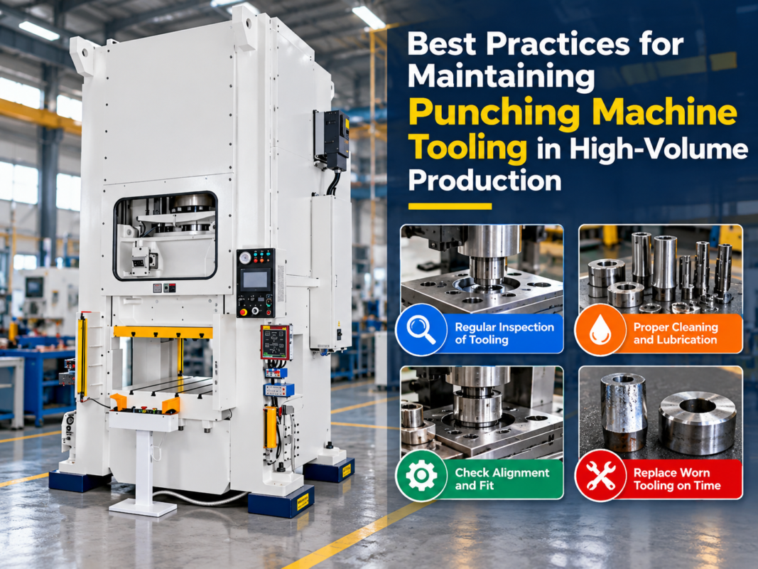
In the realm of modern metal fabrication, the press brake stands as a cornerstone of production. However, the machine itself is only as capable as the tooling it employs. Press brake tooling selection for common bend applications is a critical process that dictates the accuracy, efficiency, and safety of the bending operation. Tooling refers to the punches (upper tools) and dies (lower tools) that interface directly with the sheet metal to deform it into a specific shape. At HARSLE, we emphasize that understanding the synergy between the machine’s hydraulic force and the tool’s geometric precision is the first step toward achieving high-quality results.
The technical foundation of tooling lies in its material composition and heat treatment. Most professional-grade tools are manufactured from high-carbon steel or alloy steels like 42CrMo, which are then induction hardened to withstand immense pressure. The hardness typically ranges between 45-52 HRC, ensuring that the tool maintains its profile over thousands of cycles. When selecting tooling, one must consider the bending method: air bending, bottoming, or coining. Air bending is the most common in modern CNC environments because it allows for a wide range of angles using a single set of tools, whereas bottoming and coining provide higher precision but require specific tool sets for every angle and thickness.
Furthermore, the compatibility of the tooling system—whether it be Amada-style, European Precision, or New Standard—is paramount. Each system has unique clamping requirements and height specifications. A mismatch here can lead to uneven pressure distribution or even catastrophic tool failure. This guide aims to provide a deep dive into the parameters that govern successful tooling selection, ensuring that fabricators can optimize their HARSLE press brakes for any common bend application.
Core Parameters in Tooling Selection
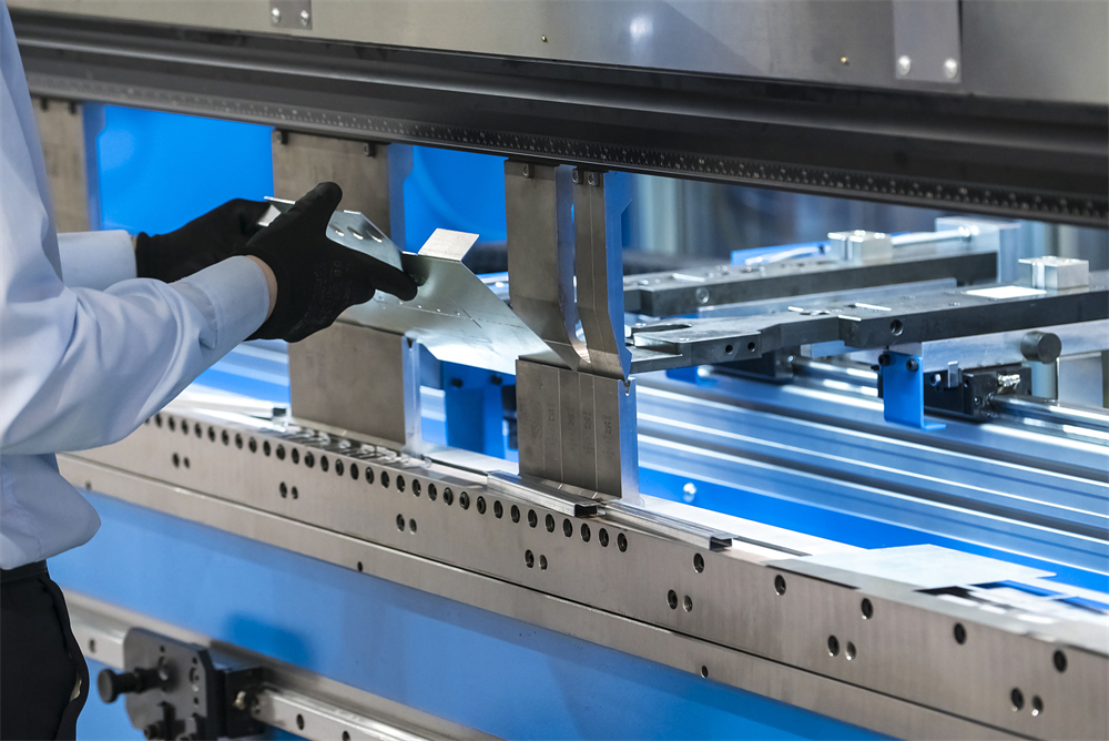
When approaching press brake tooling selection for common bend applications, several core parameters must be evaluated. The first and most influential is the V-opening width of the lower die. The V-opening (V) determines the internal radius of the bend and the amount of force required. As a general rule of thumb, the V-opening should be approximately 8 times the material thickness (T) for mild steel. For thinner materials, this ratio might drop to 6x, while for thicker or high-tensile materials, it may increase to 10x or 12x to prevent cracking and reduce tonnage requirements.
The second parameter is the punch tip radius. The punch radius should ideally be close to the natural internal radius created during air bending. If the punch radius is too small (a “sharp” punch), it can crease the material, leading to structural weakness and inaccurate bend angles due to excessive springback. Conversely, a punch radius that is too large may result in a bend that does not conform to the desired specifications. For most common applications, a punch radius that is roughly 60% to 80% of the material thickness is a safe starting point for air bending.
Thirdly, the tool angle must be considered. In air bending, the tool angle (usually 85°, 88°, or 30° for acute bends) must be smaller than the desired final angle to account for springback. For example, to achieve a 90° bend in stainless steel, which has significant springback, an 88° or even an 85° die is often used. The height of the tools, both the punch and the die, also plays a role in the “open height” of the press brake. Deep box bending requires tall punches (gooseneck punches) to avoid interference with the previously bent sides of the workpiece.
The Role of Tooling Geometry
The geometry of the punch—whether it is a straight punch, an acute punch, or a gooseneck punch—determines the complexity of the shapes you can create. Straight punches are versatile for simple 90-degree bends, while gooseneck punches are essential for creating U-profiles or deep channels where a standard punch would collide with the metal. The die geometry is equally important; multi-V dies offer versatility for shops handling various thicknesses, while single-V dies provide better stability and are easier to align for high-precision runs.
Calculation Method for Tonnage and Tooling Limits
Accurate calculation is the backbone of safe press brake operation. The most critical calculation is the bending force, or tonnage, required for a specific job. Overloading a tool is a common cause of premature wear and dangerous tool breakage. The standard formula for calculating the required tonnage (P) per meter for mild steel is:
P = (650 x S² x L) / V
Where:
P = Tonnage (kN)
S = Material thickness (mm)
L = Length of the bend (m)
V = V-opening width (mm)
For example, if you are bending 3mm mild steel over a 24mm V-opening for a length of 1 meter, the calculation would be: (650 x 3² x 1) / 24 = 243.75 kN, which is approximately 25 tons. It is vital to ensure that the selected punch and die are rated for this tonnage. Most high-quality tools have their maximum load capacity (expressed in tons per meter) laser-etched on the tool body. Always leave a safety margin of at least 20% to account for variations in material tensile strength.
Another essential calculation is the inner bend radius (Ri). In air bending, the inner radius is typically about 1/6th of the V-opening width (Ri = V / 6). This approximation helps engineers design parts that will actually fit together after fabrication. If the design requires a specific radius that differs significantly from the natural air-bend radius, the tooling selection must be adjusted accordingly, perhaps moving toward bottoming or using a different V-opening.
Parameter Table for Common Bend Applications
The following table provides a quick reference for press brake tooling selection for common bend applications using mild steel (Tensile strength approx. 450 MPa). Note that for stainless steel, tonnage should be increased by approximately 50%.
| Material Thickness (mm) | Recommended V-Opening (mm) | Inner Bend Radius (mm) | Tonnage per Meter (Tons) | Min. Flange Length (mm) |
|---|---|---|---|---|
| 1.0 | 6 – 8 | 1.0 – 1.3 | 6 – 8 | 4.5 |
| 1.5 | 10 – 12 | 1.6 – 2.0 | 9 – 11 | 7.0 |
| 2.0 | 16 | 2.6 | 13 – 15 | 11.0 |
| 3.0 | 24 | 4.0 | 20 – 25 | 17.0 |
| 4.0 | 32 | 5.3 | 32 – 35 | 22.0 |
| 6.0 | 50 | 8.3 | 45 – 50 | 35.0 |
| 8.0 | 63 | 10.5 | 75 – 85 | 45.0 |
| 10.0 | 80 | 13.3 | 100 – 110 | 55.0 |
| 12.0 | 100 | 16.6 | 120 – 140 | 70.0 |
Common Engineering Mistakes in Tooling Selection
Even experienced operators can fall into traps when performing press brake tooling selection for common bend applications. One of the most frequent mistakes is using a V-opening that is too small for the material thickness. While this might seem like a way to achieve a tighter radius, it exponentially increases the required tonnage, leading to “ram upset” (permanent deformation of the press brake beam) or catastrophic tool failure. It also causes significant marking on the outside of the part.
Another common error is ignoring the “minimum flange length.” Every V-opening has a minimum flange requirement; if the flange is too short, it will slip into the V-opening before the bend is completed, resulting in a distorted edge and potential damage to the die shoulders. This is especially problematic when trying to bend small parts on large dies. Always refer to the V-opening’s specifications to ensure the flange is long enough to bridge the die shoulders securely.
Neglecting tool maintenance is a third major pitfall. Over time, the shoulders of the die and the tip of the punch wear down. This wear is often uneven, occurring mostly in the center of the machine where most small parts are bent. If an operator then tries to bend a long part using worn tools, the angle will vary across the length of the workpiece. Regular inspection, cleaning, and lubrication of the tool tangs and seats are essential for maintaining the precision of your HARSLE equipment.
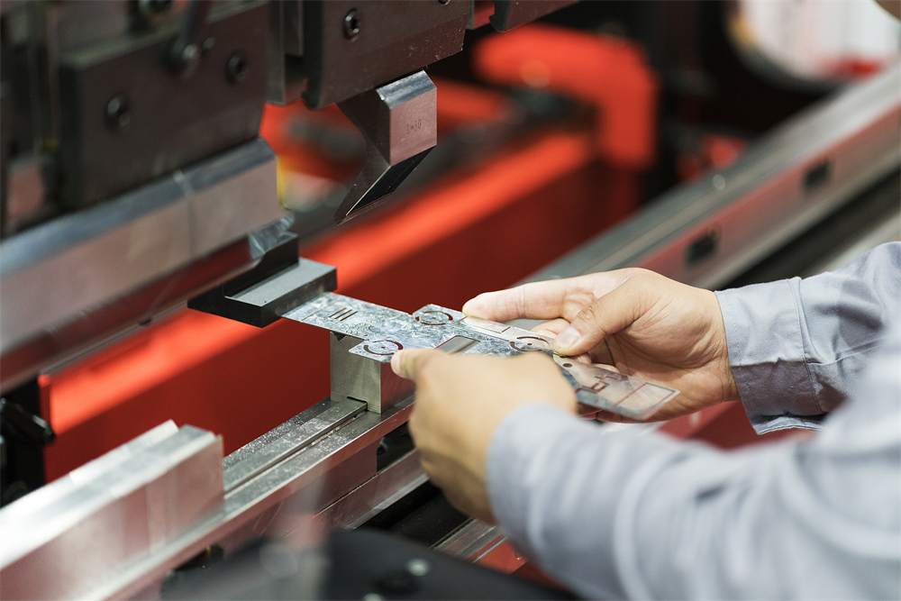
Selection Checklist for Press Brake Tooling
To ensure consistent quality, follow this comprehensive checklist during your press brake tooling selection for common bend applications:
- Material Analysis: Identify the material type (mild steel, stainless, aluminum) and its tensile strength. High-tensile materials require stronger tools and larger V-openings.
- Thickness Verification: Measure the actual thickness of the sheet metal, as “gauge” thickness can vary between batches.
- Tonnage Check: Calculate the required tonnage and verify it against the tool’s rated capacity and the machine’s limits.
- V-Opening Selection: Apply the 8x rule for mild steel and ensure the V-opening supports the minimum flange length required by the part design.
- Punch Radius Selection: Choose a punch radius that avoids material fracturing and matches the desired internal radius as closely as possible.
- Interference Check: For complex bends or deep boxes, use 2D or 3D simulation software to ensure the punch and workpiece do not collide during the stroke.
- Angle Consideration: Select a tool angle that allows for sufficient over-bending to compensate for the material’s springback.
- Tooling Style Compatibility: Ensure the punch and die tangs match the clamping system of your HARSLE press brake (e.g., Euro-style, Wilia).
- Surface Finish Requirements: If the part must be mark-free, consider using nylon inserts, urethane pads, or specialized “no-mark” dies.
- Length and Sectioning: Determine if you need full-length tools or a sectionalized set for bending boxes with return flanges.
Frequently Asked Questions (FAQ)
1. Can I use the same tooling for both mild steel and stainless steel?
Yes, you can use the same tools, but you must be aware of the differences in material behavior. Stainless steel is much harder and has more springback. You will need approximately 50% more tonnage to bend stainless steel of the same thickness as mild steel. Additionally, stainless steel can be abrasive, leading to faster wear on the die shoulders. It is often recommended to use hardened tools and potentially protective tape to prevent carbon contamination from the tools to the stainless surface.
2. What happens if I use a punch with a radius smaller than the material thickness?
Using a punch with a radius smaller than the material thickness (often called a “sharp” bend) can lead to several issues. It creates a high-stress point in the material, which can cause cracking on the outer radius, especially in aluminum or high-carbon steel. It also makes the bend angle less predictable because the punch penetrates the material rather than just forming it. For most applications, the punch radius should be at least equal to or slightly larger than the material thickness for the best results.
3. How do I know when my press brake tooling needs to be replaced?
Signs that tooling needs replacement include visible nicks or cracks on the punch tip or die shoulders, inconsistent bend angles across the length of a single part, and the need for excessive tonnage to achieve a standard bend. You can also use a precision template or a profile projector to check the tool’s geometry against its original specifications. If the punch tip has flattened or the die shoulders have become “valleyed,” it is time for regrinding or replacement.
4. Why is the 8x rule for V-openings so important?
The 8x rule (V = 8 x T) is the “sweet spot” for air bending mild steel. It provides a balance between manageable tonnage requirements and a reasonable inner bend radius. If the V-opening is smaller (e.g., 6x), the tonnage increases significantly. If it is larger (e.g., 12x), the tonnage decreases, but the inner radius becomes much larger, and the minimum flange length increases. Following this rule ensures the longevity of both your tools and your HARSLE press brake.
5. What is the advantage of using sectionalized tooling?
Sectionalized tooling consists of several smaller pieces of punches and dies that can be combined to reach a specific length. This is incredibly useful for bending boxes or four-sided shapes where a solid long punch would interfere with the side flanges. It also makes the tools lighter and easier for a single operator to handle and change, improving setup times and safety.
6. How does the die angle affect the bending process?
The die angle is primarily chosen to accommodate springback. In air bending, the material is pushed into the die but does not touch the bottom. Therefore, an 85-degree die can be used to make any angle from 180 degrees down to 90 degrees. The extra 5 degrees (from 90 to 85) allows the machine to over-bend the metal so that when the pressure is released, it “springs back” to exactly 90 degrees. Without this clearance, you could never achieve a perfect 90-degree bend in materials with high elasticity.