Choosing the Right Hydraulic Press for Metal Fabrication: A Technical Buyer’s Guide

Technical Overview: The Foundation of Hydraulic Press Selection
In the realm of modern metalworking, the hydraulic press stands as a cornerstone of versatility and power. Unlike mechanical presses that rely on a flywheel and crankshaft to deliver energy, hydraulic presses utilize Pascal’s principle to generate massive force through fluid pressure. For any facility manager or engineer, choosing hydraulic press metal fabrication: a technical buyer’s journey begins with understanding how these machines translate hydraulic energy into controlled, linear motion. The ability to deliver full tonnage throughout the entire stroke makes the hydraulic press indispensable for operations ranging from simple punching to complex deep drawing.
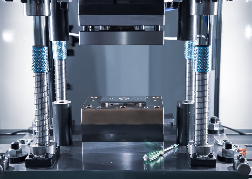
HARSLE has pioneered the integration of advanced hydraulic manifolds and PLC-controlled systems to ensure that modern presses are not just powerful, but also precise. A technical overview must acknowledge the three primary frame configurations: C-frame (gap frame), H-frame (straight-side), and the four-column (four-post) design. Each structure offers distinct advantages in terms of rigidity, accessibility, and resistance to deflection. For instance, a C-frame provides excellent three-sided access for manual part loading, whereas an H-frame is engineered to minimize frame stretching under high-tonnage loads, ensuring tighter tolerances for precision components.
Beyond the frame, the hydraulic circuit itself is a critical technical consideration. Modern systems often feature variable displacement pumps and proportional valves. These components allow the operator to fine-tune the approach speed, pressing speed, and return speed. This level of control is vital when working with sensitive materials or intricate dies where a sudden impact could lead to material fracture or tool wear. Understanding the synergy between the hydraulic power unit (HPU) and the electrical control system is the first step in making an informed procurement decision.
Finally, the evolution of Industry 4.0 has introduced smart monitoring into hydraulic presses. Today’s technical buyer must look for machines equipped with pressure transducers, linear encoders, and thermal sensors. These features provide real-time data on the pressing cycle, allowing for predictive maintenance and quality assurance. When evaluating a press, one must consider not just the raw force it can exert, but the intelligence with which that force is applied and monitored throughout the production lifecycle.
Core Parameters: Defining Machine Capability
When choosing hydraulic press metal fabrication: a technical buyer’s focus must shift to the specific parameters that define the machine’s operational envelope. The most prominent parameter is **Tonnage**. This is the maximum force the press can exert. However, a common mistake is selecting a press that operates at its maximum capacity 100% of the time. For longevity and safety, it is recommended to select a machine where the required application force is approximately 70-80% of the press’s rated capacity. This buffer prevents premature wear on seals, valves, and the frame itself.
The **Stroke Length** is another vital parameter. It defines the total distance the ram can move from its fully retracted position to its fully extended position. In hydraulic presses, the stroke is fully adjustable, which is a significant advantage over mechanical alternatives. This adjustability allows for faster cycle times by limiting the ram’s travel to only what is necessary for the specific part being produced. Buyers must ensure the stroke is long enough to accommodate both the height of the tooling and the depth of the part being formed.
**Daylight (Open Height)** and **Bed Area** determine the physical size of the workpieces and dies the machine can handle. Daylight is the distance between the bed (bolster) and the ram in its fully retracted position. If the daylight is too small, you won’t be able to fit large dies or remove deep-drawn parts. The bed area must be large enough to support the die set without excessive overhang, which could lead to uneven pressure distribution. HARSLE offers customizable bed sizes to meet specific industrial requirements, ensuring that the machine footprint is optimized for the workshop floor.
Lastly, **Speed** parameters—specifically approach speed, pressing speed, and return speed—dictate the machine’s productivity. High-speed approach saves time, while a controlled pressing speed is essential for quality metal flow. The return speed influences the overall cycle time. For high-volume production, a press with a fast-acting hydraulic system and rapid-fill valves is essential to maintain competitive output rates. Technical buyers should analyze these speeds in millimeters per second (mm/s) to calculate potential parts-per-hour (PPH) metrics.
Calculation Method: Determining Required Force
Accurate force calculation is the heart of choosing hydraulic press metal fabrication: a technical buyer’s responsibility. Underestimating the force leads to incomplete parts and stalled production, while overestimating leads to unnecessary capital expenditure. The calculation method varies depending on the operation: punching, bending, or drawing.
1. Punching and Shearing Force
To calculate the force required for punching a hole, the formula is: Force (P) = L × t × τ. Where L is the perimeter of the cut (e.g., π × diameter for a round hole), t is the material thickness, and τ (tau) is the shear strength of the material. It is crucial to use the shear strength rather than the tensile strength, as shearing occurs when the material’s shear limit is exceeded. Always add a 20% safety factor to account for tool dulling and material variations.
2. Bending Force (V-Bending)
For V-bending, the formula is more complex: P = (K × S × b × t²) / V. Here, K is a constant (usually 1.33), S is the ultimate tensile strength, b is the bend length, t is thickness, and V is the V-die opening width. The width of the V-opening significantly impacts the required force; a narrower V-opening requires substantially more pressure to achieve the same bend. This calculation helps in selecting the right press brake or hydraulic press for heavy-duty folding tasks.
3. Deep Drawing Force
Deep drawing involves pushing a blank into a die cavity. The force required depends on the blank diameter, the punch diameter, the material thickness, and the yield strength. Additionally, one must account for the **Blank Holder Force (BHF)**. The BHF is necessary to prevent wrinkling as the material flows into the die. In many hydraulic presses, this is handled by a secondary hydraulic cushion located beneath the main bed. The total press capacity must be the sum of the drawing force and the blank holder force.
Parameter Table: Comparison of Hydraulic Press Types
The following table provides a technical comparison of the most common hydraulic press configurations used in metal fabrication to assist in the selection process.
| Feature | C-Frame (Gap) Press | H-Frame (Straight-Side) | 4-Column Press |
|---|---|---|---|
| Tonnage Range | 5 – 250 Tons | 50 – 2000+ Tons | 10 – 5000+ Tons |
| Rigidity | Moderate (Subject to ‘Yawning’) | High (Minimal Deflection) | Very High (Uniform Loading) |
| Accessibility | Excellent (3-Sided) | Limited (Front/Back) | Excellent (4-Sided) |
| Precision | Standard | High | Very High |
| Common Apps | Punching, Riveting, Assembly | Heavy Blanking, Automotive | Deep Drawing, Forging, Molding |
| Footprint | Compact | Large | Medium to Large |
Common Engineering Mistakes in Press Selection
One of the most frequent mistakes when choosing hydraulic press metal fabrication: a technical buyer’s pitfall is ignoring **Off-Center Loading**. Hydraulic presses are generally designed for central loading. When a die is placed off-center, it creates a moment arm that can cause the ram to tilt, leading to premature wear on the bushings and seals, and potentially scoring the cylinder walls. If your process requires off-center loading, you must specify a press with extra-long gibbing or a four-column design that can better resist these lateral forces.
Another common oversight is neglecting the **Hydraulic Cooling System**. In high-cycle applications, the hydraulic oil generates significant heat. If the oil temperature exceeds 60°C (140°F), its viscosity drops, leading to internal leakage, reduced precision, and accelerated degradation of seals. Buyers often forget to check if the press includes an air-cooled or water-cooled heat exchanger. For tropical climates or 24/7 production environments, an oversized cooling system is a wise investment that pays for itself in reduced downtime.
Furthermore, many buyers fail to consider the **Decompression Cycle**. When a press reaches its target pressure, the hydraulic fluid and the machine frame store a significant amount of elastic energy. If the pressure is released instantaneously, it creates a “hydraulic shock” (water hammer) that can rupture pipes and damage valves. A well-engineered press, like those from HARSLE, incorporates a decompression circuit that slowly bleeds off pressure before the ram moves, ensuring smooth operation and machine longevity.
Lastly, the importance of **Oil Filtration** is often underestimated. Contaminated oil is the leading cause of hydraulic component failure. A technical buyer should look for systems that include high-efficiency kidney-loop filtration or at least 10-micron return line filters. Monitoring the ISO cleanliness code of the hydraulic fluid should be a standard part of the maintenance protocol, yet it is frequently ignored until a valve sticks or a pump fails.
Selection Checklist: A Step-by-Step Guide
To ensure you select the optimal machine, follow this technical checklist during your procurement process:
- Material Specifications: Define the maximum thickness, tensile strength, and shear strength of the materials you will process.
- Operation Type: Determine if you are punching, bending, drawing, or coining. This dictates the need for features like hydraulic cushions or high-speed valves.
- Tonnage Requirement: Calculate the peak force and add a 20-30% safety margin.
- Bolster and Ram Dimensions: Ensure the bed size can accommodate your largest die set with room for clamping.
- Stroke and Daylight: Verify that the ram travel and open height are sufficient for part removal and tool installation.
- Cycle Time Requirements: Calculate the required mm/s for approach and pressing to meet your production targets.
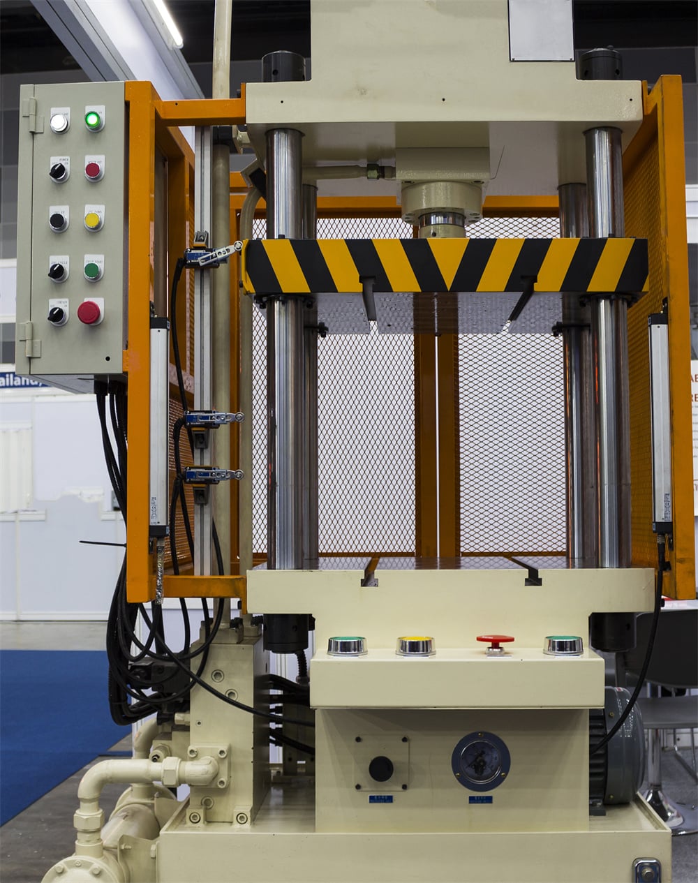
- Control System: Decide between manual controls, NC (Numerical Control), or full CNC/PLC integration for automated lines.
- Safety Features: Ensure the machine meets local safety standards (e.g., CE, OSHA) with light curtains, dual-hand tie-down controls, and safety interlocks.
- Maintenance & Support: Confirm the availability of spare parts (seals, filters, valves) and the manufacturer’s technical support reputation.
Frequently Asked Questions (FAQ)
1. What is the difference between a hydraulic press and a mechanical press?
A hydraulic press uses fluid pressure to provide constant force throughout the entire stroke, making it ideal for deep drawing and varied stroke lengths. A mechanical press uses a flywheel and linkage, delivering maximum force only at the bottom of the stroke, which is better for high-speed, shallow blanking operations.
2. How do I know if I need a 4-column press or an H-frame press?
If you need 4-sided access for large parts or automation, a 4-column press is superior. If you require maximum rigidity for high-precision, heavy-tonnage blanking where die alignment is critical, an H-frame (straight-side) press is the better choice due to its robust frame construction.
3. Can I use a hydraulic press for high-speed punching?
While traditional hydraulic presses are slower than mechanical ones, modern “high-speed” hydraulic presses equipped with accumulator circuits and advanced servo-hydraulics can achieve impressive cycle rates, though they may still not match the raw speed of a dedicated mechanical punching center.
4. Why is my hydraulic press losing pressure?
Pressure loss is usually attributed to internal leakage in the cylinder seals, a malfunctioning relief valve, or a worn-out hydraulic pump. Regular inspection of the oil for contaminants and checking seal integrity are essential maintenance steps.
5. What kind of hydraulic oil should I use?
Most industrial hydraulic presses use an anti-wear (AW) hydraulic oil, typically ISO VG 32, 46, or 68, depending on the ambient temperature and the manufacturer’s specifications. Always refer to the HARSLE manual for the specific grade required for your machine model.
6. Is it possible to automate a hydraulic press?
Yes, modern hydraulic presses are easily integrated into automated cells. They can be equipped with PLC interfaces to communicate with robotic loaders, coil feeders, and transfer systems, making them a vital part of an automated metal fabrication line.


