Comprehensive Guide: How to Prevent Hydraulic Press Pressure Loss in Daily Operation


The Critical Importance of Pressure Stability in Hydraulic Presses
In the world of metal fabrication, the hydraulic press stands as a cornerstone of industrial productivity. Whether it is used for deep drawing, stamping, forging, or molding, the machine’s ability to maintain consistent hydraulic pressure is paramount to the quality of the finished product. When a hydraulic press experiences pressure loss, it is not merely a mechanical hiccup; it is a significant threat to operational efficiency, safety, and the bottom line. Understanding how to Prevent Hydraulic Press Pressure Loss In Daily Operation is essential for any facility manager or machine operator working with HARSLE equipment.
Pressure loss, often referred to as ‘pressure drop’ or ‘pressure bleed-down,’ occurs when the system cannot sustain the force required to perform its task. This can lead to incomplete forming, inconsistent part dimensions, and increased scrap rates. Furthermore, a system that struggles to maintain pressure often works harder, leading to overheating, accelerated wear on pumps, and potential catastrophic failure of hydraulic components. By implementing a rigorous maintenance strategy, operators can ensure that their HARSLE hydraulic presses operate at peak performance for decades.
The physics of a hydraulic press relies on Pascal’s Law, which states that pressure applied to a confined fluid is transmitted undiminished in every direction. In a perfect system, this pressure remains constant until the work is completed. However, in the real-world environment of a busy factory, factors such as heat, vibration, contamination, and component wear constantly work against this ideal state. Therefore, preventing pressure loss is an active, daily process rather than a reactive one.
HARSLE machines are engineered with high-precision components designed to minimize internal leakage, but even the best machinery requires diligent care. This guide will delve into the technical nuances of hydraulic systems, electrical controls, and mechanical structures to provide a comprehensive roadmap for maintaining pressure integrity. By following these protocols, you can maximize uptime and ensure that every cycle of your press delivers the exact force required.
Daily Inspection Protocols: The First Line of Defense
The most effective way to Prevent Hydraulic Press Pressure Loss In Daily Operation is through a disciplined daily inspection routine. Before the first shift begins, a visual and auditory sweep of the machine can reveal early warning signs that might otherwise lead to a mid-day breakdown. Operators should be trained to look for ‘telltale’ signs of trouble, such as small puddles of oil, unusual noises, or erratic gauge readings.
Start with a visual inspection of all external hydraulic lines and connections. Even a minor weep at a fitting can escalate into a significant pressure leak under high-load conditions. Check the hydraulic reservoir levels; a sudden drop in oil level is the most obvious indicator of an external leak. However, if the oil level is stable but pressure is still dropping, the issue likely lies within the internal circuitry of the valves or the cylinder itself.
Auditory inspections are equally important. A healthy hydraulic system has a consistent, rhythmic hum. If you hear high-pitched whining, it may indicate pump cavitation—a condition where air bubbles form in the oil, leading to erratic pressure and internal damage. A ‘banging’ or ‘knocking’ sound could suggest water hammer or loose mechanical components. Identifying these sounds early allows for intervention before the pressure loss becomes critical.
Finally, monitor the pressure gauges during a dry cycle. The needle should rise smoothly to the set point and hold steady without flickering or drifting downward. If the pressure gauge shows a slow decline while the ram is held in position, it is a clear signal that fluid is bypassing a seal or a valve. Documenting these daily findings in a logbook helps maintenance teams track trends and predict when a component might be nearing the end of its service life.
Hydraulic System Checks: Managing Seals, Valves, and Pumps
The hydraulic circuit is the heart of the press, and its integrity is vital to preventing pressure loss. The three primary areas of concern are the seals, the control valves, and the hydraulic pump. Each of these components must function in harmony to maintain the high-pressure environment required for metal fabrication.
Seal Integrity and Replacement
Seals are the most common point of failure in any hydraulic system. In a hydraulic press, seals are found in the main cylinder (piston seals and rod seals), in the pump, and within every valve. Over time, the friction of the ram moving up and down, combined with the heat generated by the hydraulic fluid, causes these seals to harden, crack, or wear down. When a piston seal fails, oil leaks from the high-pressure side of the cylinder to the low-pressure side, causing the ram to ‘drift’ or lose its holding force.
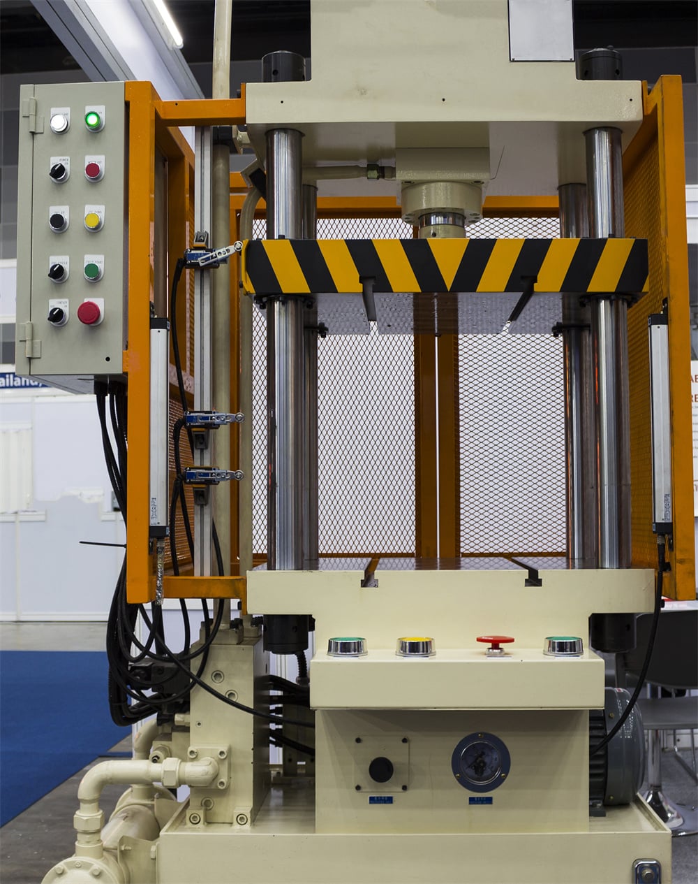
To prevent this, it is crucial to use high-quality replacement seals that are compatible with the specific hydraulic fluid used in your HARSLE press. Furthermore, the environment around the rod seal must be kept clean. Dust and metal shavings can adhere to the ram and be pulled into the seal, acting like sandpaper and destroying the seal’s surface. Installing rod wipers and ensuring the ram is polished and free of nicks can significantly extend seal life.
Valve Performance and Contamination
Directional control valves and pressure relief valves are responsible for directing the flow of oil and maintaining the desired pressure levels. If a valve spool becomes scarred or if a piece of debris gets lodged in the valve seat, the valve will not close completely. This creates a ‘leak path’ that allows pressure to bleed back to the reservoir. Contamination is the number one enemy of hydraulic valves. Even microscopic particles can cause ‘stiction’ or wear down the precision-machined surfaces of the valve internals.
Regularly checking the filtration system is essential. High-efficiency filters should be used to keep the oil at a cleanliness level of at least ISO 4406 18/16/13. If the pressure relief valve is constantly ‘chattering’ or opening at a lower pressure than its setting, it may need to be disassembled, cleaned, and recalibrated. A failing relief valve is a frequent cause of sudden pressure loss during the pressing stroke.
Pump Efficiency and Cavitation
The hydraulic pump is the source of the flow that creates pressure. As pumps wear, their internal clearances increase, leading to internal leakage (slippage). This means the pump has to spin faster to maintain the same pressure, which generates more heat and further accelerates wear. Monitoring the pump’s case drain flow is a technical way to measure this internal wear. If the flow from the case drain increases significantly, the pump is likely reaching the end of its life and will soon be unable to maintain system pressure.
Electrical and Control System Maintenance
Modern HARSLE hydraulic presses rely on sophisticated electrical systems to monitor and control pressure. Sometimes, what appears to be a mechanical pressure loss is actually an electrical fault. Sensors, PLCs, and solenoid valves must all be in perfect working order to ensure the machine responds correctly to the operator’s commands.
Pressure transducers are the ‘eyes’ of the control system. They convert hydraulic pressure into an electrical signal that the PLC reads. If a transducer is miscalibrated or failing, it may report that the pressure is lower than it actually is, causing the system to overcompensate, or it may fail to trigger the pump to maintain pressure. Regularly calibrating these sensors against a known-good manual gauge is a critical maintenance step.
Solenoid valves are the actuators that move the hydraulic spools. If the electrical coil in a solenoid is weak or if the wiring is frayed, the valve may not shift fully or may shift slowly. This can lead to a delay in pressure buildup or a failure to hold pressure. Ensure that all electrical cabinets are kept clean and cool, as excessive heat can degrade electronic components and lead to erratic behavior in the control circuit.
Furthermore, the PLC software logic should be protected. Ensure that the parameters for pressure dwell times and decompression cycles are correctly set. If the decompression cycle is too fast, it can cause hydraulic shock (water hammer), which can damage seals and fittings, leading to future pressure leaks. A well-tuned electrical control system acts as a safeguard for the mechanical and hydraulic components.
Mechanical Integrity: Frame, Ram, and Alignment
While the hydraulic fluid does the work, the mechanical structure of the press provides the necessary resistance. If the mechanical integrity of the press is compromised, it can lead to uneven pressure distribution and perceived pressure loss. The frame of a HARSLE press is designed for high rigidity, but it must be maintained to ensure this remains the case.
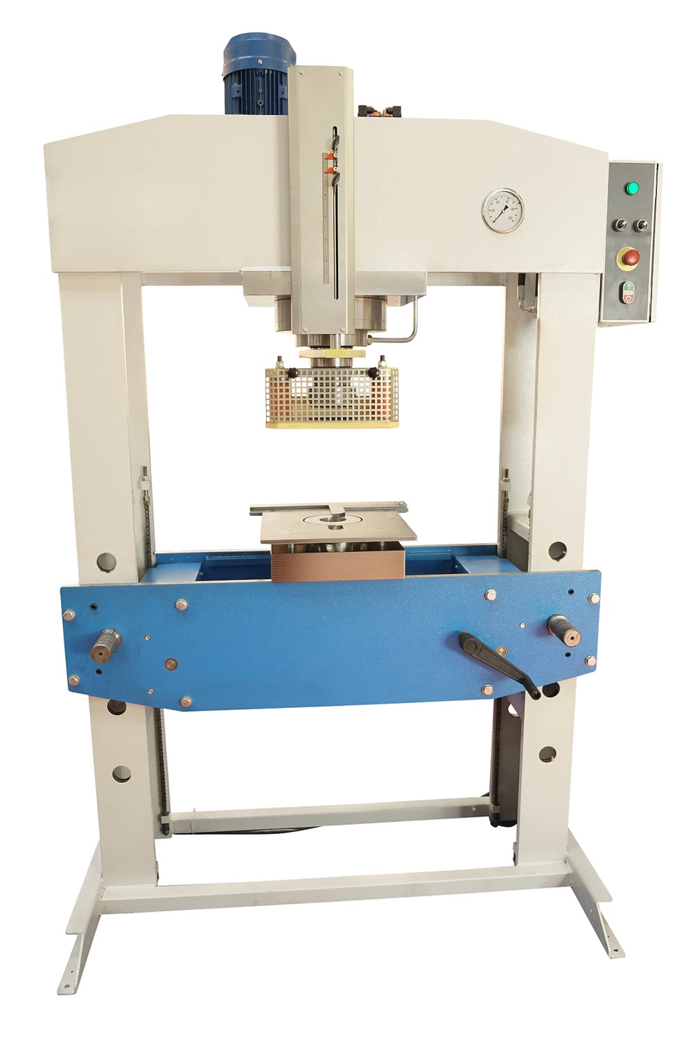
Check the mounting bolts of the main cylinder and the tie rods (if applicable). If the cylinder is allowed to move even a fraction of a millimeter, it can cause misalignment of the ram. Misalignment leads to side-loading on the piston seals, which causes them to wear unevenly and fail prematurely. Use a precision level and dial indicators to check the parallelism between the ram and the bolster plate regularly.
The guide rails (gibs) are another critical mechanical component. These rails ensure that the ram moves perfectly vertically. If the gibs are loose or worn, the ram can tilt during the pressing stroke. This tilt creates an uneven gap between the piston and the cylinder wall, allowing oil to bypass the seals more easily. Properly adjusting the gib clearances and ensuring they are well-lubricated is a fundamental part of preventing pressure-related issues.
Finally, inspect the bolster plate and the ram face for any deformations or ‘dishing.’ If the pressing surfaces are not flat, the pressure will not be applied uniformly to the workpiece. This can lead to the machine’s sensors detecting a pressure drop as the material deforms into the gaps, even if the hydraulic system is technically holding steady. Maintaining a flat, clean working surface is essential for consistent results.
Comprehensive Lubrication Plan
Lubrication is often discussed in the context of mechanical gears, but in a hydraulic press, the hydraulic oil itself is the primary lubricant for the pump and valves. However, the external moving parts, such as the ram guides and linkage pins, require their own lubrication schedule to prevent friction-induced heat and wear.
The choice of hydraulic oil is critical. It must have the correct viscosity index to operate within the temperature range of your facility. If the oil is too thin (low viscosity), it will leak past seals and valve spools more easily, leading to pressure loss. If it is too thick, the pump will struggle to move it, leading to cavitation. HARSLE recommends specific oil grades that balance lubricity with pressure-holding capabilities. Anti-wear (AW) additives are also essential to protect the high-pressure contact points within the pump.
For the mechanical guides, a high-pressure grease or a dedicated way-lube should be used. Many HARSLE presses feature automatic lubrication systems. It is a common mistake to assume these systems are always working. Daily checks should be made to ensure the grease reservoir is full and that the distribution lines are not blocked or broken. A dry guide rail will quickly overheat, causing the metal to expand and potentially seizing the ram, which creates an immense load on the hydraulic system and leads to pressure spikes followed by failure.
Oil oxidation is another factor to consider. Over time, hydraulic oil reacts with oxygen, especially at high temperatures, forming sludge and varnish. This varnish can coat valve spools, making them ‘sticky’ and preventing them from sealing properly. Regular oil analysis—sending a sample to a lab—can tell you the exact condition of your oil and when it needs to be replaced, preventing pressure loss before it starts.
Troubleshooting Signals: Identifying Early Warning Signs
To effectively Prevent Hydraulic Press Pressure Loss In Daily Operation, operators must be able to interpret the ‘language’ of the machine. Several signals indicate that the system is beginning to lose its ability to hold pressure. Recognizing these early can save thousands of dollars in repair costs and lost production time.
- Increased Cycle Times: If the press takes longer to reach its target pressure than it did a month ago, the pump is likely losing efficiency or there is an internal leak.
- Excessive Heat: If the hydraulic reservoir or the valve manifold feels unusually hot to the touch (above 140°F / 60°C), energy is being wasted. This heat is often the result of oil being forced through a small leak or a partially closed valve, which drops the pressure.
- Ram Drift: With the pump off and the ram in a raised position, observe if it slowly creeps downward. This is a definitive sign of cylinder seal failure or a leaking check valve.
- Spongy Operation: If the ram movement feels ‘bouncy’ or ‘spongy,’ there is likely air trapped in the hydraulic lines. Air is compressible, whereas oil is not; air in the system will always lead to inconsistent pressure.
- Foaming Oil: Look through the sight glass of the reservoir. If the oil looks milky or foamy, air is being drawn into the pump intake, which will cause immediate pressure fluctuations.
When these signals appear, the first step should always be to check the simplest solutions: tighten fittings, check oil levels, and inspect filters. If the problem persists, a systematic isolation of the hydraulic circuits using pressure gauges at different test points can help pinpoint exactly which valve or cylinder is at fault.
Maintenance Schedule Table
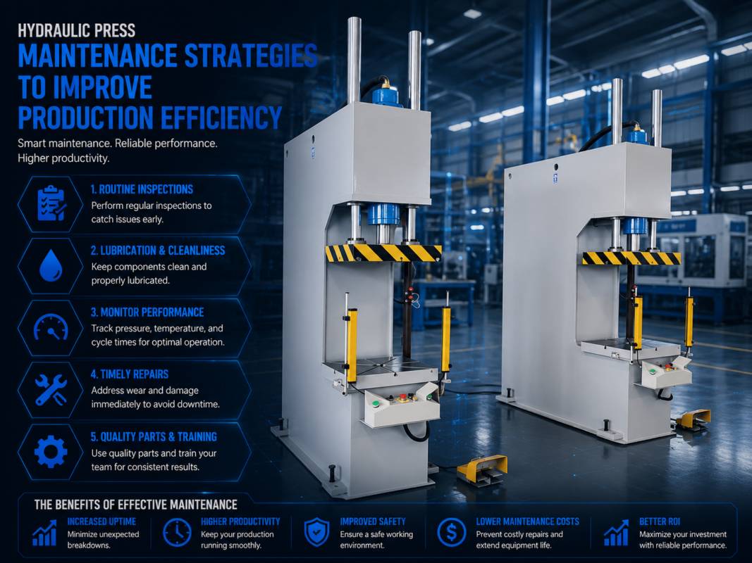
A structured maintenance schedule is the backbone of machine longevity. Use the following table as a baseline for your HARSLE hydraulic press maintenance program.
| Frequency | Task Description | Target Component |
|---|---|---|
| Daily | Check oil level and temperature | Hydraulic Reservoir |
| Daily | Inspect for external leaks at hoses/fittings | Entire Hydraulic Circuit |
| Daily | Verify lubrication system operation | Ram Guides / Gibs |
| Daily | Monitor pressure gauge for stability | Control Panel |
| Weekly | Clean the ram and inspect for scoring | Main Cylinder Rod |
| Weekly | Check electrical connections and sensors | PLC / Transducers |
| Monthly | Inspect and clean air breathers | Reservoir Tank |
| Monthly | Check bolt torque on main frame/cylinder | Mechanical Structure |
| Quarterly | Analyze hydraulic oil for contamination | Hydraulic Fluid |
| Quarterly | Check and adjust gib clearances | Ram Guides |
| Annually | Replace hydraulic filters and oil (if needed) | Filtration System |
| Annually | Calibrate pressure gauges and transducers | Instrumentation |
Frequently Asked Questions (FAQ)
1. Why does my hydraulic press lose pressure only after it gets hot?
This is usually due to oil viscosity thinning. As hydraulic oil heats up, its viscosity decreases. If your seals or pump clearances are slightly worn, the thinner oil can bypass them more easily than when the oil is cold. This indicates that it may be time to replace seals or check if you are using the correct grade of oil for your environment.
2. How often should I change the hydraulic oil to prevent pressure loss?
There is no one-size-fits-all answer, but generally, oil should be changed every 2,000 to 4,000 operating hours. However, the best practice is to perform oil analysis every six months. This will tell you if the oil is still chemically stable and free of contaminants, potentially saving you from an unnecessary oil change or alerting you to a problem early.
3. Can air in the system cause a total loss of pressure?
While air usually causes erratic pressure or ‘sponginess,’ a large amount of air can cause the pump to lose its prime, leading to a total loss of pressure. Air also causes cavitation, which can physically destroy the internal components of the pump very quickly, leading to a permanent loss of pressure capability.
4. What is the most common cause of internal pressure leakage?
The most common cause is a worn piston seal inside the main cylinder. Because this leak is internal, you won’t see oil on the floor, but the press will fail to hold pressure during the dwell cycle. Another common culprit is a piece of debris stuck in the pressure relief valve seat.
5. Is it safe to tighten a leaking hydraulic fitting while the press is under pressure?
Absolutely not. Never attempt to tighten fittings or perform maintenance while the system is pressurized. Hydraulic injection injuries are extremely dangerous and can be fatal. Always shut down the pump and bleed off all stored pressure (including accumulator pressure) before performing any repairs.
Conclusion: Sustaining Peak Performance
To Prevent Hydraulic Press Pressure Loss In Daily Operation requires a combination of technical knowledge, diligent observation, and proactive maintenance. By understanding that pressure loss is a symptom of underlying issues—whether it be contamination, heat, or mechanical wear—operators can take the necessary steps to protect their equipment. HARSLE hydraulic presses are built to withstand the rigors of industrial use, but their precision depends on the care they receive.
Implementing the daily checks, maintaining oil cleanliness, and adhering to a strict lubrication and inspection schedule will not only prevent pressure loss but also extend the overall lifespan of the machine. Remember that a well-maintained press is a safe press and a profitable press. By investing time in maintenance today, you avoid the high costs of emergency repairs and production downtime tomorrow. Keep your hydraulic systems clean, cool, and sealed, and your HARSLE machinery will continue to deliver the power and precision your fabrication processes demand.