Understanding Laser Cutting Machine Accuracy, Speed, and Kerf in Industrial Applications

Technical Overview of Industrial Laser Cutting
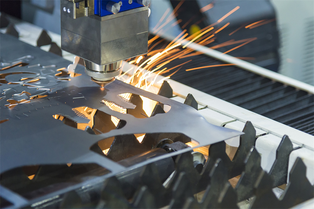
In the realm of modern manufacturing, the laser cutting machine has emerged as an indispensable tool for precision metal fabrication. At its core, laser cutting is a thermal process that utilizes a concentrated beam of light—typically generated by a fiber or CO2 source—to melt, burn, or vaporize material along a predetermined path. For industrial giants and small-scale workshops alike, the ability to master the relationship between accuracy, speed, and kerf is what separates high-quality production from costly scrap. HARSLE, a leader in metal fabrication machinery, emphasizes that understanding these technical nuances is critical for maximizing the ROI of any CNC fiber laser system.
The evolution of laser technology has seen a significant shift from traditional CO2 lasers to high-efficiency fiber lasers. Fiber lasers offer superior beam quality, which directly influences the focus diameter and energy density. This technological leap has allowed for tighter tolerances and faster processing speeds, especially in thin to medium-thickness metals. However, with increased power comes the need for more sophisticated control systems. Modern industrial applications demand not just raw power, but the intelligent application of that power to ensure that every cut meets stringent aerospace, automotive, or medical standards.

When we discuss Understanding Laser Cutting Machine Accuracy, Speed, and Kerf in Industrial Applications, we are looking at a triad of variables that are deeply interconnected. A change in one inevitably affects the others. For instance, increasing the cutting speed might reduce the kerf width but could potentially compromise the dimensional accuracy if the machine’s motion system cannot keep up with the acceleration demands. Conversely, prioritizing extreme accuracy often requires a reduction in speed to minimize mechanical vibrations and thermal distortion. This guide delves into these parameters to provide engineers and operators with a comprehensive framework for optimization.
Core Parameters: Accuracy, Speed, and Kerf
Understanding Accuracy in Laser Cutting
Accuracy in laser cutting is often misunderstood as a single metric, but it is actually composed of two distinct components: positioning accuracy and repeatability. Positioning accuracy refers to the machine’s ability to move the cutting head to a specific coordinate within the working area. Repeatability, on the other hand, is the machine’s ability to return to that same coordinate multiple times with minimal deviation. In industrial settings, a high-quality HARSLE laser machine typically offers positioning accuracy within ±0.03mm and repeatability within ±0.02mm.
Several factors influence these metrics. The mechanical rigidity of the machine bed is paramount; a heavy-duty, heat-treated frame prevents deformations that could lead to misalignment over time. Furthermore, the quality of the linear guides and servo motors plays a crucial role. High-end systems utilize helical racks and pinions combined with absolute encoders to ensure that the software’s commands are translated into precise physical movement. Without this mechanical integrity, even the most advanced laser source will fail to produce accurate parts.
The Dynamics of Cutting Speed
Cutting speed is the primary driver of productivity in any fabrication shop. It is defined as the linear distance the laser head travels per unit of time, usually measured in meters per minute (m/min) or inches per minute (IPM). The optimal speed is determined by the laser power, the material type, the material thickness, and the type of assist gas used (Oxygen, Nitrogen, or Compressed Air). For example, cutting 1mm stainless steel with a 3kW fiber laser can reach speeds exceeding 40m/min, whereas 20mm carbon steel requires a much slower, more controlled approach.
If the speed is too high, the laser may not fully penetrate the material, resulting in incomplete cuts or excessive dross (hardened melt) on the bottom of the workpiece. If the speed is too low, the heat-affected zone (HAZ) increases, leading to thermal deformation and a wider, rougher kerf. Finding the “sweet spot” involves balancing the energy input per unit of length to ensure a clean, dross-free edge while maintaining the highest possible throughput.
Defining and Managing Kerf Width
The “kerf” is the width of the material that is removed during the cutting process. In laser cutting, the kerf is typically very narrow, ranging from 0.1mm to 0.5mm depending on the material and laser parameters. While it may seem negligible, failing to account for the kerf in the CAD/CAM software will result in parts that are slightly smaller than intended and holes that are slightly larger. This is particularly critical for interlocking parts or components requiring a press-fit.
Kerf width is influenced by the focal spot size, the nozzle diameter, the gas pressure, and the cutting speed. A smaller focal spot, achieved through high-quality optics, results in a narrower kerf. However, as the material thickness increases, the kerf naturally widens because the beam must be focused deeper into the material, and the assist gas must clear a larger volume of molten metal. Understanding how to measure and compensate for this width is a fundamental skill for any CNC operator.
Calculation Method for Precision Cutting
To achieve the highest level of precision, operators must utilize specific calculation methods to adjust their machine settings. The most common calculation involves Kerf Compensation. The formula for the adjusted tool path is: Adjusted Dimension = Target Dimension + (Kerf Width / 2) for external profiles, and Adjusted Dimension = Target Dimension – (Kerf Width / 2) for internal holes. Most modern CNC software, such as CypCut or Lantek, allows operators to input a “Kerf Offset” value which automatically handles these calculations.
Another critical calculation is the Heat Input Index, which helps in predicting thermal distortion. This is calculated as: Heat Input = (Laser Power / Cutting Speed). By maintaining a consistent heat input index across different thicknesses, operators can ensure uniform edge quality. Furthermore, calculating the Focus Position is essential. For thin materials, the focus is usually on the surface (0mm), but for thicker materials, the focus may be set to -50% of the material thickness to ensure the energy is distributed effectively through the entire cut depth.
Industrial Parameter Reference Table
The following table provides a general guideline for HARSLE fiber laser machines (3kW Fiber Laser source) across common industrial materials. Note that these values may vary based on specific alloy compositions and gas purity.
| Material Type | Thickness (mm) | Cutting Speed (m/min) | Assist Gas | Gas Pressure (Bar) | Approx. Kerf (mm) |
|---|---|---|---|---|---|
| Carbon Steel | 1.0 | 35-45 | Oxygen | 0.5 – 0.8 | 0.12 |
| Carbon Steel | 6.0 | 2.5 – 3.2 | Oxygen | 0.6 – 1.0 | 0.25 |
| Carbon Steel | 12.0 | 1.2 – 1.6 | Oxygen | 0.5 – 0.7 | 0.40 |
| Stainless Steel | 1.0 | 40-50 | Nitrogen | 12 – 16 | 0.10 |
| Stainless Steel | 5.0 | 4.0 – 6.0 | Nitrogen | 14 – 18 | 0.22 |
| Stainless Steel | 10.0 | 1.0 – 1.5 | Nitrogen | 16 – 20 | 0.35 |
| Aluminum | 2.0 | 15-20 | Nitrogen/Air | 12 – 15 | 0.15 |
| Aluminum | 8.0 | 1.5 – 2.2 | Nitrogen | 15 – 18 | 0.30 |
Common Engineering Mistakes in Laser Operations
Even with high-end equipment, certain engineering oversights can lead to poor results. One of the most common mistakes is ignoring thermal expansion. When cutting large nests of small parts on a single sheet, the cumulative heat can cause the sheet to expand. If the machine does not account for this, the parts cut at the end of the program may be dimensionally inaccurate compared to those cut at the beginning. Implementing a “cooling path” or jumping between different areas of the sheet can mitigate this issue.
Another frequent error is incorrect focal point selection. Many operators assume that the focus should always be on the top surface. However, for thick stainless steel using nitrogen, the focus should actually be deep inside the material to help the high-pressure gas push the molten metal out of the bottom. Using the wrong focus results in a “V-shaped” cut rather than a perpendicular edge, which significantly impacts the accuracy of the final part.
Finally, neglecting nozzle maintenance is a silent killer of precision. A slightly damaged or off-center nozzle will distort the flow of assist gas, causing the laser beam to interact inconsistently with the material. This leads to an asymmetrical kerf, where one side of the cut is cleaner than the other. Regular inspection and calibration of the nozzle centering are mandatory for industrial-grade accuracy.
Selection Checklist for Industrial Laser Machines
When selecting a laser cutting machine for industrial applications, use the following checklist to ensure the equipment meets your accuracy and speed requirements:
- Laser Source Brand & Power: Ensure the source (e.g., IPG, Raycus) is rated for your maximum material thickness with at least a 20% power reserve.
- Motion System: Look for high-precision linear guides (like HIWIN or PMI) and reputable servo motors (Yaskawa or Delta).
- Frame Construction: A heavy-duty, plate-welded frame that has been stress-relieved in a high-temperature furnace is essential for long-term stability.
- Control Software: Ensure the software supports automatic kerf compensation, nesting optimization, and real-time power modulation.
- Cooling System: A dual-circuit water chiller is necessary to keep both the laser source and the cutting head at stable temperatures, preventing focal drift.
- After-Sales Support: Verify that the manufacturer, like HARSLE, provides comprehensive technical training and readily available spare parts.
Frequently Asked Questions
How does material type affect kerf width?
Different materials have different thermal conductivity and melting points. For example, aluminum is highly reflective and conductive, which often results in a slightly wider kerf compared to stainless steel because the heat spreads more rapidly away from the point of impact. Carbon steel cut with oxygen also tends to have a wider kerf due to the exothermic reaction that occurs during the burning process.
Can I achieve zero kerf in laser cutting?
No, zero kerf is physically impossible in laser cutting because the process relies on the removal of material to create a separation. However, by using ultra-short pulse lasers (femtosecond lasers) or very high-frequency fiber lasers with specialized optics, the kerf can be reduced to as little as 20-50 microns in specialized micro-machining applications.
Why is my laser cutting speed slower than the manufacturer’s specs?
Manufacturer specifications are often based on ideal conditions: brand new nozzles, 99.99% pure assist gas, and high-grade material. If your speed is lower, check for gas impurities, lens cleanliness, or inconsistencies in the material’s surface (such as heavy rust or scale on hot-rolled steel), all of which can impede the cutting process.
How often should I calibrate the accuracy of my HARSLE machine?
For high-precision industrial work, a quick check of the nozzle centering and focal point should be done daily. A full mechanical calibration, checking the squareness of the axes and the tension of the drive belts or racks, should be performed every six months or after any significant mechanical collision.
What is the relationship between laser power and accuracy?
Higher laser power does not inherently mean higher accuracy. In fact, higher power can lead to more heat-related issues. However, higher power allows for faster cutting speeds on thicker materials, which can actually improve accuracy by reducing the time the heat has to conduct into the surrounding material, thereby narrowing the heat-affected zone.


