A Technical Guide to Laser Cutting Machine Nozzle Selection and Alignment

Technical Overview of Laser Cutting Nozzles
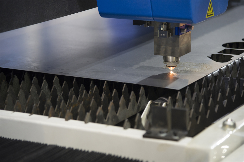
In the realm of high-precision metal fabrication, the laser cutting machine stands as a pinnacle of engineering. However, the efficiency of even the most advanced fiber laser system is heavily dependent on a seemingly small component: the nozzle. The nozzle is the final interface between the laser cutting head and the workpiece. Its primary functions are twofold: first, to direct the auxiliary gas (oxygen, nitrogen, or air) into the kerf to facilitate the cutting process; and second, to protect the internal optical components, specifically the focusing lens, from molten metal backsplash and debris.
A Technical Laser Cutting Machine Nozzle Selection Alignment strategy is essential for achieving clean cuts, minimizing dross, and maximizing processing speed. The nozzle controls the shape and velocity of the gas jet, which in turn influences the cooling of the material and the removal of molten slag. Without a perfectly centered and appropriately sized nozzle, the laser beam may clip the internal walls of the nozzle, leading to beam distortion, reduced power density, and potential damage to the cutting head itself. For HARSLE machines, maintaining the integrity of the nozzle is a fundamental requirement for operational excellence.

The material composition of the nozzle also plays a critical role. Most high-quality nozzles are manufactured from high-conductivity copper or chrome-plated copper. Copper is preferred due to its excellent thermal and electrical conductivity, which is necessary for the capacitive height sensing systems used in modern fiber lasers. Chrome plating is often applied to increase the nozzle’s resistance to heat and to prevent slag from adhering to the surface, thereby extending its service life in high-power applications.
The Role of Nozzle Geometry in Gas Dynamics
The internal geometry of a nozzle—whether it is a single-layer or double-layer design—dictates the flow characteristics of the auxiliary gas. A single-layer nozzle is typically used for fusion cutting with nitrogen or compressed air. In this process, the gas is used to mechanically blow away the molten material. The flow must be laminar and high-velocity to ensure a clean edge. Conversely, a double-layer nozzle is designed for flame cutting, primarily used with oxygen on carbon steel. The double-layer structure creates a stable gas shield that prevents turbulence and ensures a consistent supply of oxygen to the cutting zone, which is vital for the exothermic reaction required to cut thick plates.
Core Parameters for Nozzle Selection
Selecting the right nozzle involves balancing several technical parameters, including diameter, height, and the type of material being processed. The nozzle diameter is perhaps the most critical variable. It typically ranges from 1.0mm to 5.0mm. A smaller nozzle diameter (1.0mm to 1.5mm) concentrates the gas flow, providing high pressure and high velocity, which is ideal for thin materials (under 3mm). This concentration ensures a narrow kerf and a high-quality finish. However, if the nozzle is too small for the material thickness, the gas flow will be insufficient to clear the slag, leading to dross formation.
As material thickness increases, the nozzle diameter must also increase. For plates thicker than 6mm, nozzles in the 2.0mm to 3.0mm range are common. Larger nozzles allow for a higher volume of gas flow at lower pressures, which is necessary to penetrate the depth of the cut. However, using a nozzle that is too large for thin material can result in excessive gas consumption and a wider heat-affected zone (HAZ), potentially warping the workpiece. Therefore, A Technical Laser Cutting Machine Nozzle Selection Alignment must be tailored to the specific gauge of the metal.
Another core parameter is the stand-off distance, or the nozzle height above the workpiece. This distance is usually maintained between 0.5mm and 1.5mm. If the nozzle is too close, there is a risk of collision or slag buildup blocking the orifice. If it is too far, the gas jet disperses before reaching the kerf, losing its effectiveness in clearing molten metal. Modern HARSLE laser cutters utilize sensitive capacitive sensors to maintain a constant stand-off distance, but the operator must ensure the nozzle is clean and undamaged for these sensors to function accurately.
Calculation Method for Gas Flow and Nozzle Sizing
While many operators rely on manufacturer presets, understanding the underlying calculation method for gas flow can help in optimizing specialized cutting tasks. The gas flow rate (Q) through a nozzle can be approximated using the formula for flow through an orifice, considering the nozzle diameter (d) and the gas pressure (P). The relationship is generally proportional to the square of the diameter; thus, doubling the nozzle diameter quadruples the gas consumption for the same pressure.
In technical terms, the Reynolds number of the gas jet determines whether the flow is laminar or turbulent. For high-speed fiber laser cutting, a laminar flow is preferred to maintain a stable cutting environment. Engineers calculate the required gas velocity based on the viscosity of the molten metal and the thickness of the plate. For example, when cutting 10mm stainless steel with nitrogen, the gas pressure must be high enough (often 12-18 bar) to overcome the surface tension of the molten stainless steel. The nozzle diameter must be large enough (e.g., 2.5mm) to provide the volume of gas necessary to maintain this pressure throughout the depth of the kerf.
Nozzle Parameter Table for Common Materials
The following table provides a general guideline for nozzle selection based on material type and thickness for a standard 3kW to 6kW fiber laser cutting machine. Note that these values may vary based on specific machine configurations and gas purity.
| Material Type | Thickness (mm) | Nozzle Type | Diameter (mm) | Gas Type | Pressure (Bar) |
|---|---|---|---|---|---|
| Stainless Steel | 1 – 3 | Single | 1.2 – 1.5 | Nitrogen | 10 – 14 |
| Stainless Steel | 4 – 8 | Single | 2.0 – 2.5 | Nitrogen | 14 – 18 |
| Carbon Steel | 1 – 5 | Double | 1.2 – 1.5 | Oxygen | 0.5 – 1.5 |
| Carbon Steel | 6 – 12 | Double | 2.0 – 3.0 | Oxygen | 0.5 – 1.0 |
| Aluminum | 1 – 4 | Single | 1.5 – 2.0 | Nitrogen/Air | 12 – 16 |
| Brass/Copper | 1 – 3 | Single | 1.2 – 1.5 | Nitrogen | 15 – 20 |
Common Engineering Mistakes in Nozzle Management
One of the most frequent mistakes in laser cutting operations is the continued use of a deformed or contaminated nozzle. Even a microscopic nick on the nozzle orifice can cause the auxiliary gas to exit at an angle or with turbulence. This results in an asymmetrical cut, where one side of the part is clean while the other has significant dross. Operators often attempt to compensate for this by slowing down the cutting speed or increasing laser power, which only exacerbates the problem and leads to higher operational costs.
Another common error is improper alignment, often referred to as “beam decentering.” If the laser beam is not perfectly centered within the nozzle orifice, it will heat one side of the nozzle more than the other. This not only distorts the gas flow but can also lead to the beam reflecting off the internal wall of the nozzle, causing a “ghost beam” that ruins the cut quality and can damage the protective windows. Regular checks using the “tape test” are mandatory to prevent this issue. Furthermore, neglecting to calibrate the capacitive sensor after changing a nozzle can lead to height errors, resulting in inconsistent focal points and poor cut quality.
A Technical Guide to Nozzle Alignment: The Tape Test
Alignment is the cornerstone of A Technical Laser Cutting Machine Nozzle Selection Alignment. The most reliable manual method for checking alignment is the tape test. To perform this, the operator places a piece of transparent adhesive tape over the nozzle orifice. A low-power laser pulse (shot) is then fired. The resulting mark on the tape reveals the position of the beam relative to the nozzle’s center.
- Preparation: Ensure the nozzle is clean and the machine is in a safe state for a pulse test.
- Application: Apply a small piece of tape firmly over the nozzle tip.
- Pulse: Fire a short, low-power burst (usually 5-10% power for 0.1 seconds).
- Inspection: Remove the tape and inspect the hole. The hole should be a perfect circle and perfectly centered within the indentation made by the nozzle rim.
- Adjustment: If the hole is off-center, use the adjustment screws on the cutting head (usually X and Y axes) to shift the nozzle position. Repeat the test until the beam is perfectly centered.
Failure to align the nozzle correctly results in “directional cutting issues,” where the machine cuts well in the X-direction but poorly in the Y-direction, or vice versa. This is a tell-tale sign that the gas flow and the laser beam are not coaxial.
Selection Checklist for Machine Operators
To ensure consistent performance, operators should follow this checklist before starting any significant production run:
- Verify Material Compatibility: Is the nozzle type (single/double) correct for the material and gas?
- Check Orifice Integrity: Inspect the nozzle under magnification for roundness and absence of slag.
- Confirm Diameter: Does the nozzle diameter match the thickness of the plate according to the technical chart?
- Perform Alignment: Has a tape test been conducted since the last nozzle change or shift start?
- Calibrate Height Sensor: Has the “follow-up” or capacitive sensor been calibrated for the specific nozzle installed?
- Check Gas Purity: Ensure the auxiliary gas is free of moisture and oil, which can contaminate the nozzle and lens.
Frequently Asked Questions (FAQ)
How often should I replace my laser cutting nozzle?
The lifespan of a nozzle depends on the power level, material type, and cutting environment. In high-power applications (above 6kW), a nozzle may need replacement every 8-24 hours of active cutting. However, if a collision occurs or if slag buildup cannot be removed, it must be replaced immediately. Using a worn nozzle significantly reduces cut quality and increases gas consumption.
Why does my nozzle keep getting covered in slag?
Slag buildup is usually caused by an incorrect stand-off distance, insufficient gas pressure, or piercing too close to the nozzle. When the laser pierces the metal, molten material can blow back. Using a “power pierce” setting or applying anti-splatter spray to the nozzle can help mitigate this. Additionally, ensure your cooling system is working correctly, as an overheated nozzle attracts more slag.
Can I use a single nozzle for cutting carbon steel with oxygen?
While it is physically possible, it is not recommended. Single nozzles are designed for high-pressure nitrogen flow. Oxygen cutting requires a more stable, lower-pressure flow that a double-layer nozzle provides. Using a single nozzle for oxygen cutting often results in a violent reaction, poor surface finish, and rapid nozzle degradation.
What happens if the nozzle diameter is too small?
If the diameter is too small, the gas flow will be restricted. This leads to insufficient cooling of the cut zone and inadequate removal of molten metal. The result is usually a “welded” cut where the slag re-solidifies in the kerf, making it impossible to remove the part from the skeleton. It also increases the risk of the laser beam clipping the nozzle.
Does the brand of the nozzle matter?
Yes. High-quality nozzles, such as those provided or recommended by HARSLE, are manufactured with tighter tolerances for concentricity and surface finish. Cheap, third-party nozzles often have internal burrs or inconsistent diameters, which can lead to unpredictable cutting results and potential damage to expensive optical components.


