
How to Maintain Press Brake Electrical Components Safely and Efficiently


The Critical Importance of Electrical Maintenance in Press Brakes
In the modern metal fabrication landscape, the press brake is no longer just a mechanical beast of burden; it is a sophisticated piece of technology governed by intricate electrical systems. To maintain press brake electrical components safely and efficiently is to ensure the heartbeat of your production line remains steady. Neglecting these components can lead to catastrophic failures, expensive downtime, and, most importantly, significant safety risks to operators. At HARSLE, we emphasize that a well-maintained electrical system is the foundation of precision bending and long-term machine reliability.
Electrical systems in press brakes manage everything from the high-voltage motors that drive hydraulic pumps to the sensitive low-voltage signals processed by the CNC controller. When dust, heat, or vibration compromises these circuits, the machine’s accuracy suffers. A minor voltage fluctuation can cause a backgauge to misalign by fractions of a millimeter, leading to scrapped parts and wasted material. Therefore, understanding the synergy between electrical health and mechanical output is the first step for any maintenance professional.
Safety is the paramount concern when dealing with industrial electricity. Press brakes operate on high-voltage three-phase power, which carries the risk of arc flashes and electrocution if handled improperly. By establishing a rigorous maintenance routine, you are not just protecting the machine; you are protecting your workforce. Efficient maintenance means identifying a frayed wire or a failing contactor before it causes a short circuit or a fire. This proactive approach transforms maintenance from a reactive chore into a strategic advantage.
Finally, the longevity of your investment depends on electrical integrity. Components like Programmable Logic Controllers (PLCs), Variable Frequency Drives (VFDs), and touch-screen HMIs are expensive to replace. Regular cleaning, tightening, and thermal monitoring can extend the lifespan of these parts by years. In this guide, we will delve into the specific steps required to keep your HARSLE press brake running at peak performance through meticulous electrical care.
Daily Inspection: The First Line of Defense
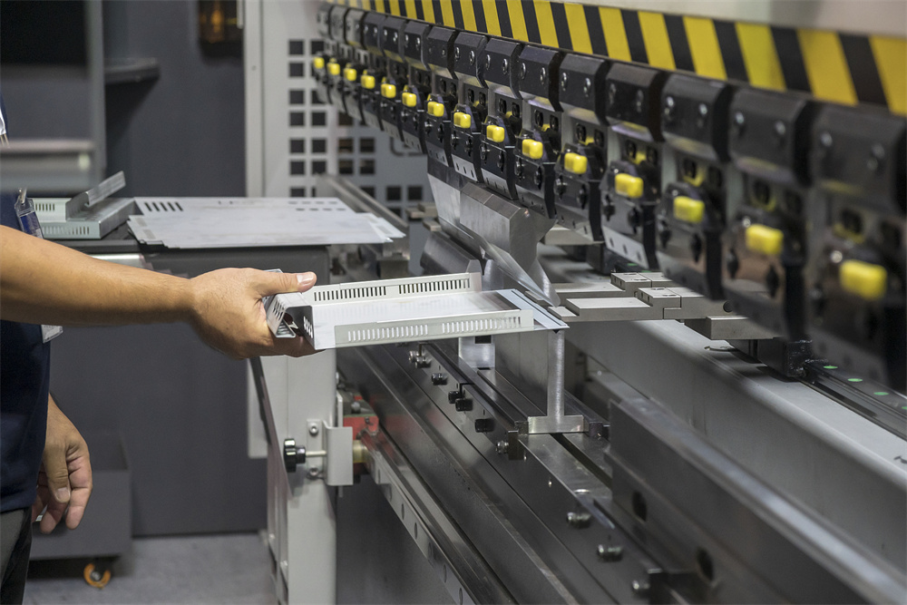
The daily inspection is a non-negotiable ritual for any shop aiming to maintain press brake electrical components safely and efficiently. This process should begin before the machine is even powered on. A visual sweep of the exterior can reveal immediate red flags, such as loose conduits, damaged cables, or signs of oil ingress into electrical junction boxes. Oil is a silent killer of electrical insulation, causing it to degrade and eventually fail.
Once the visual check is complete, the power-on sequence provides critical data. Listen for unusual sounds from the electrical cabinet, such as buzzing or humming, which could indicate a struggling transformer or a loose contactor. Observe the HMI (Human Machine Interface) for any immediate error codes or warnings. Modern HARSLE machines are equipped with diagnostic software that can pinpoint electrical anomalies during the boot-up phase. If the screen flickers or takes an unusually long time to load, it may indicate a power supply issue or a failing internal battery in the CNC unit.
Testing the emergency stop (E-stop) buttons and safety light curtains is the most critical part of the daily electrical check. These are not just mechanical switches; they are part of a complex safety circuit. Ensure that depressing any E-stop immediately cuts power to the drive system and that the light curtains correctly interrupt the cycle when the beam is broken. If these electrical safety features fail, the machine must be locked out immediately until repairs are made.
Lastly, check the cooling fans on the electrical cabinet. These fans are essential for dissipating the heat generated by VFDs and power supplies. If a fan is clogged with dust or has stopped spinning, the internal temperature of the cabinet can rise rapidly, leading to component overheating and premature failure. A quick wipe of the fan filters every morning can prevent hours of troubleshooting later in the day.
Comprehensive Hydraulic, Electrical, and Mechanical Checks
Electrical Cabinet and Wiring Integrity
The electrical cabinet is the brain of the press brake. To maintain press brake electrical components safely and efficiently, this area must be kept pristine. Open the cabinet (following all LOTO protocols) and use compressed air—at low pressure and moisture-free—to blow out accumulated dust. Dust can be conductive, especially in metalworking environments where fine metallic particles float in the air. A buildup of conductive dust on a circuit board can cause a short circuit that destroys the PLC.
Check all terminal blocks for tightness. Vibration from the machine’s operation can cause screw terminals to loosen over time. A loose connection creates high resistance, which generates heat and can eventually melt the wire insulation or the terminal itself. Use an infrared thermometer to scan the cabinet while the machine is under load; any “hot spots” on breakers or contactors are clear indicators of a failing component or a poor connection.
Hydraulic-Electrical Interface
The relationship between the electrical system and the hydraulic system is managed by solenoid valves. These valves receive electrical signals to open and close, directing oil flow to the cylinders. Inspect the solenoid coils for signs of overheating or discoloration. Ensure the electrical plugs connecting to these valves are secure and free of moisture. If a valve is sluggish, it may be an electrical signal issue rather than a mechanical hydraulic failure.
Mechanical Feedback Systems
Mechanical precision is maintained through electrical feedback loops. Encoders and linear scales provide the CNC with the exact position of the ram and the backgauge. These components are sensitive to vibration and contamination. Ensure that the cables for these sensors are routed away from high-voltage power lines to prevent electromagnetic interference (EMI), which can cause “ghost” movements or positioning errors. Cleaning the scales with the manufacturer-recommended solution ensures the optical or magnetic read-heads can function without interruption.
The Lubrication Plan: Supporting Electrical Longevity
While lubrication is primarily a mechanical concern, it has a direct impact on the electrical system. A poorly lubricated machine requires more torque to move the ram and backgauge, which in turn draws more current through the electrical motors and drives. By following a strict lubrication plan, you reduce the electrical load on the system, thereby helping to maintain press brake electrical components safely and efficiently.
Focus on the electric motor bearings. Most large motors in press brakes have grease nipples. Over-greasing is as dangerous as under-greasing, as excess grease can find its way into the motor windings, causing insulation failure. Use only the specified high-temperature grease and follow the interval guide provided in your HARSLE manual. Additionally, ensure that the lead screws and linear guides of the backgauge are well-lubricated to prevent the servo motors from overworking and tripping their thermal overloads.
It is also vital to ensure that lubrication systems—especially automatic ones—are electrically sound. Check the pump motor and the low-level sensors. If the electrical sensor fails to alert the operator of a low oil level, the mechanical components will seize, leading to a massive spike in electrical current that could blow fuses or damage the motor drives. Thus, the lubrication system’s electrical health is a safeguard for the entire machine.
Troubleshooting Signals and Warning Signs
Recognizing the early warning signs of electrical distress can save a shop thousands of dollars. One of the most common signals is an intermittent error code on the CNC. These “nuisance alarms” often point to a loose ground wire or a failing power supply. Never ignore these; they are the machine’s way of telling you that a component is on the verge of total failure. Investigate the root cause by checking the voltage stability at the main input.
Another signal is the smell of ozone or burning plastic. This is an emergency. It indicates that insulation is failing or a component is arcing. Immediately shut down the machine and perform a thorough inspection of the wiring harnesses and motor junction boxes. Similarly, if you notice the HMI screen dimming when the ram starts its stroke, this indicates a significant voltage drop, suggesting that the electrical service to the machine is inadequate or that the main transformer is failing.
Unusual noise from the servo motors, such as high-pitched whining or growling, often points to an electrical tuning issue or a failing encoder. In modern CNC systems, the drive parameters might need adjustment, or the feedback cable might be picking up interference. To maintain press brake electrical components safely and efficiently, use an oscilloscope or the built-in diagnostic tools of the drive software to analyze the signal quality and ensure the motor is receiving a clean, modulated wave.
Comprehensive Maintenance Schedule Table
To maintain press brake electrical components safely and efficiently, follow this structured schedule. Consistency is the key to preventing unexpected breakdowns.
| Frequency | Component | Action Required | Goal |
|---|---|---|---|
| Daily | E-Stops & Light Curtains | Functional test of all safety circuits | Operator Safety |
| Daily | Cabinet Cooling Fans | Check for operation and clean filters | Prevent Overheating |
| Weekly | External Wiring/Conduits | Visual inspection for wear or oil damage | Prevent Short Circuits |
| Monthly | Electrical Cabinet Interior | Vacuum/Blow out dust; check for loose wires | System Reliability |
| Monthly | Solenoid Valves | Check connections and thermal status | Hydraulic Control |
| Quarterly | Grounding System | Test resistance of the ground circuit | EMI Reduction |
| Bi-Annually | Main Motor Terminals | Tighten connections and check insulation | Motor Longevity |
| Annually | CNC Battery & Backup | Replace internal batteries and backup data | Data Integrity |
Frequently Asked Questions (FAQ)
1. Why does my press brake keep throwing “Low Voltage” alarms?
Low voltage alarms are often caused by an unstable power grid or an undersized transformer feeding the machine. However, it can also be caused by loose connections at the main breaker or a failing DC power supply within the cabinet. Check the incoming voltage during the machine’s peak load (when the ram is pressing) to see if there is a significant drop.
2. How often should I clean the electrical cabinet?
In a standard environment, a monthly cleaning is sufficient. However, if your shop performs grinding or welding nearby, metallic dust can accumulate quickly. In such cases, a weekly check and cleaning are recommended to maintain press brake electrical components safely and efficiently. Always use dry, low-pressure air or a specialized vacuum.
3. Can I replace electrical components myself?
Basic components like fuses or standard relays can be replaced by a qualified maintenance technician. However, complex parts like the PLC, VFD, or CNC motherboard should only be handled by certified professionals or HARSLE technicians to ensure correct parameter configuration and to avoid voiding the warranty.
4. What is the danger of ignoring a flickering HMI screen?
A flickering screen usually indicates a failing 24V DC power supply or a loose ribbon cable. If the power supply fails completely during a bend cycle, the machine may lose its position, potentially damaging the tooling or the workpiece, and creating a safety hazard as the ram might not return to its home position correctly.
5. How do I prevent electromagnetic interference (EMI)?
To prevent EMI, ensure that all shielded cables are properly grounded at one end. Keep low-voltage signal wires (like those for encoders) physically separated from high-voltage power lines. Ensure the machine itself is connected to a dedicated, high-quality earth ground as specified in the HARSLE installation manual.
Conclusion: The Path to Electrical Excellence
To maintain press brake electrical components safely and efficiently is a continuous commitment to excellence. By integrating these daily, weekly, and monthly tasks into your shop’s culture, you ensure that your HARSLE press brake remains a precise and reliable tool for years to come. Remember that electricity is a powerful force that requires respect; always prioritize safety protocols, use the right tools, and never hesitate to consult with experts when a problem exceeds your internal capabilities.
Investing time in electrical maintenance pays dividends in the form of reduced repair costs, higher part quality, and a safer working environment. As the industry moves toward even more complex Industry 4.0 integrations, the health of your machine’s electrical system will become the primary factor in your competitive edge. Keep your cabinets clean, your connections tight, and your sensors calibrated—your press brake will thank you with decades of flawless service.


