Hydraulic Press Troubleshooting Guide: Common Faults and Solutions for Industrial Efficiency

Technical Overview of Hydraulic Press Systems
Hydraulic presses are the workhorses of the metal fabrication industry, utilizing Pascal’s Law to generate massive amounts of force for forging, stamping, bending, and deep drawing. At its core, a hydraulic press consists of a pump that moves hydraulic fluid through a system of valves and cylinders to actuate a ram. While these machines are designed for durability, the high-pressure environment and repetitive cycles eventually lead to wear and tear. Understanding the technical nuances of the hydraulic circuit—including the reservoir, pump, control valves, and actuators—is the first step in effective Hydraulic Press Troubleshooting : Common Faults Solutions.
Modern hydraulic presses, such as those manufactured by HARSLE, integrate advanced PLC (Programmable Logic Controller) systems and proportional valve technology to ensure precision. However, even the most sophisticated systems can encounter issues like pressure drops, overheating, or abnormal noise. A technical overview must acknowledge that the hydraulic fluid is the lifeblood of the machine. It doesn’t just transmit power; it also lubricates moving parts and dissipates heat. Therefore, many troubleshooting scenarios begin with an analysis of the oil’s condition, viscosity, and contamination levels.
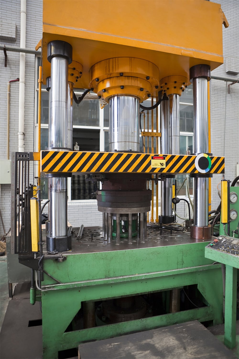
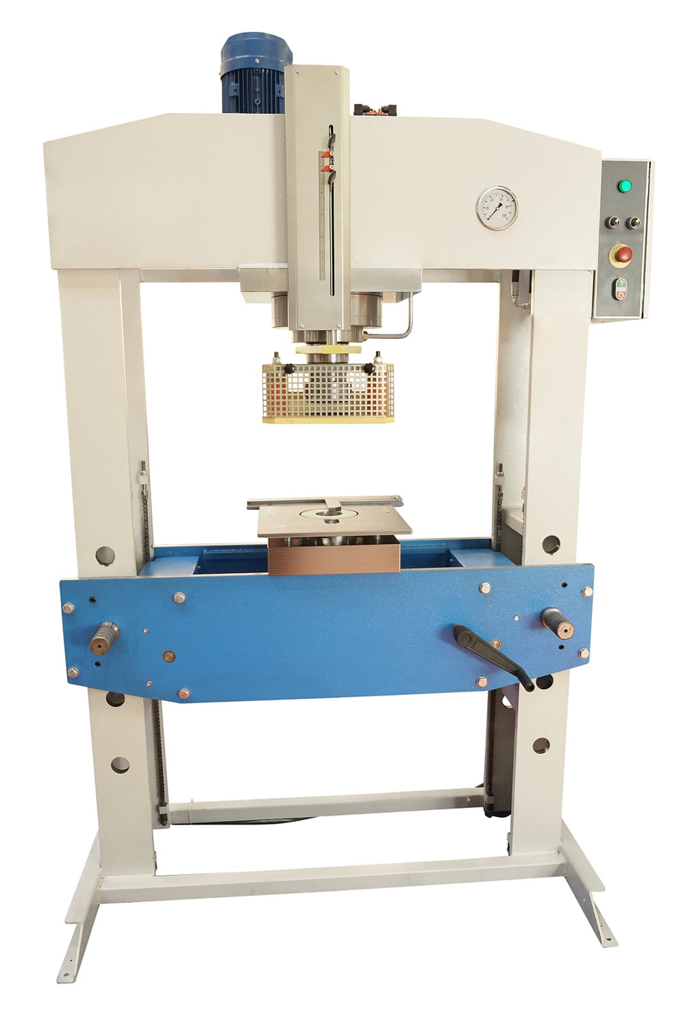
The structural integrity of the frame—whether it is a C-frame, H-frame, or four-column design—also plays a role in performance. Misalignment in the frame can lead to uneven wear on the seals and guide rails, manifesting as erratic ram movement. Technical diagnostics often involve checking the parallelism of the bolster and the ram to ensure that the force is distributed evenly across the workpiece. This guide aims to provide a comprehensive roadmap for identifying these mechanical and hydraulic discrepancies before they lead to costly downtime.
Core Parameters of Hydraulic Presses
To troubleshoot a hydraulic press effectively, one must understand its core operating parameters. These parameters define the machine’s capabilities and serve as the baseline for diagnostic testing. The primary parameter is the Nominal Force, usually measured in tons or kilonewtons (kN). This is the maximum force the press can exert. If a press fails to reach its nominal force, the troubleshooting process focuses on the relief valve settings, pump efficiency, or internal cylinder leakage.
Another critical parameter is the Stroke Length, which is the total distance the ram can travel. Issues with stroke limits often point to faulty limit switches or errors in the PLC programming. Daylight (the distance between the bed and the ram in its fully retracted position) and Table Size are also vital, as they dictate the size of the dies and workpieces. If the ram does not return to its full daylight position, it may indicate a vacuum lock or a mechanical obstruction in the guide system.
Speed parameters, including Approach Speed, Pressing Speed, and Return Speed, are essential for production efficiency. A deviation in these speeds usually suggests a problem with the flow control valves or a clogged suction filter. By monitoring these core parameters during a standard cycle, operators can pinpoint exactly where the system is underperforming, making the Hydraulic Press Troubleshooting : Common Faults Solutions process much more targeted and efficient.
Calculation Method for Hydraulic Performance
Troubleshooting often requires a mathematical approach to verify if the machine is performing according to its design specifications. The most fundamental calculation is the relationship between pressure, area, and force. The formula is F = P × A, where F is the force (in Newtons), P is the pressure (in Pascals), and A is the effective area of the piston (in square meters). If the pressure gauge shows the correct reading but the press isn’t delivering the required force, the problem likely lies in the mechanical friction or a bypass in the cylinder seals.
To calculate the required motor power for the hydraulic pump, the formula is Power (kW) = (Flow (L/min) × Pressure (bar)) / 600. This is crucial when troubleshooting overheating issues. If the motor is drawing more power than calculated, it indicates excessive internal friction or a pump that is working against a blocked line. Furthermore, calculating the Cycle Time involves dividing the stroke length by the various speeds (approach, pressing, return). If the actual cycle time exceeds the calculated time, it points toward flow inefficiencies or slow-acting solenoid valves.
Another important calculation is the Oil Compression Factor. In very high-pressure systems, hydraulic oil can compress by about 0.5% per 1,000 psi. While this seems negligible, in large-volume cylinders, it can cause a delay in pressure build-up. Understanding these calculations allows maintenance teams to distinguish between inherent physical limitations and actual mechanical faults, ensuring that troubleshooting efforts are grounded in physics.
Hydraulic Press Parameter Table
The following table outlines standard parameters for various classes of hydraulic presses. Use this as a reference when diagnosing performance issues to see if your machine is operating within typical industrial ranges.
| Press Capacity (Tons) | Max Pressure (MPa) | Ram Stroke (mm) | Approach Speed (mm/s) | Working Speed (mm/s) | Motor Power (kW) |
|---|---|---|---|---|---|
| 100T | 25 | 500 | 120 | 10-15 | 11 |
| 200T | 25 | 600 | 150 | 8-12 | 15 |
| 500T | 31.5 | 800 | 200 | 5-10 | 37 |
| 1000T | 31.5 | 1000 | 250 | 4-8 | 75 |
| 2000T | 31.5 | 1200 | 300 | 3-6 | 110 |
Note: These values are representative of HARSLE standard models. Specific custom machines may vary based on application requirements like deep drawing or high-speed stamping.
Common Engineering Mistakes in Hydraulic Press Operation
One of the most frequent engineering mistakes is Overloading the Press. Operators often attempt to perform tasks that exceed the machine’s nominal capacity, leading to structural deformation or catastrophic seal failure. Even if the relief valve prevents immediate damage, consistent operation at 100% capacity shortens the lifespan of every component. It is recommended to operate at 80% of the rated capacity for long-term reliability.
Another common error is Neglecting Oil Quality. Many facilities treat hydraulic oil as a “set it and forget it” component. In reality, oil degrades due to oxidation and thermal stress. Using oil with the wrong viscosity can lead to cavitation in the pump or sluggish valve response. Furthermore, failing to change filters regularly allows microscopic particles to score the cylinder walls and valve spools, leading to internal leakage that is difficult to diagnose without a full teardown.
Incorrect Die Alignment is a mechanical mistake that has hydraulic consequences. If the dies are not centered, the ram experiences side-loading. This creates uneven pressure on the wear rings and seals, eventually causing the cylinder to leak. Engineers must ensure that the center of pressure of the workpiece aligns with the center of the ram to maintain the machine’s geometric accuracy and prevent premature wear.
Hydraulic Press Troubleshooting: Common Faults and Solutions
1. Abnormal Noise and Vibration
Abnormal noise is often the first sign of trouble. A high-pitched whining noise usually indicates Pump Cavitation, which occurs when the pump cannot draw enough oil. This could be due to a clogged suction filter, a restricted intake line, or oil that is too viscous. The solution is to clean or replace the filters and ensure the oil meets the manufacturer’s specifications.
Banging or knocking sounds often point to Air in the System. Air can enter through loose fittings or a low oil level in the reservoir. To fix this, bleed the air from the system using the bleed valves (if equipped) or by cycling the ram through its full stroke several times at low pressure. Vibration can also be caused by loose mounting bolts or a misaligned pump-motor coupling, which requires mechanical tightening and realignment.
2. Failure to Build or Maintain Pressure
If the press reaches the workpiece but cannot build pressure, the Relief Valve is the primary suspect. It may be stuck open due to contamination or set too low. Inspect the valve for debris and reset it to the correct pressure. Another possibility is Internal Cylinder Leakage. If the piston seals are worn, oil will bypass the piston, preventing pressure build-up. This can be tested by dead-heading the cylinder and checking if the return line shows excessive flow.
A failing hydraulic pump can also cause pressure loss. If the pump’s internal tolerances have increased due to wear, it will lose efficiency, especially as the oil heats up. Check the pump’s output flow against its rated capacity. If the flow drops significantly as pressure increases, the pump likely needs a rebuild or replacement.
3. Excessive Oil Temperature
Hydraulic systems typically operate best between 40°C and 55°C. If the temperature exceeds 60°C, the oil’s viscosity drops, leading to increased wear and seal failure. Overheating is often caused by a malfunctioning cooling system (either air-cooled or water-cooled). Check for clogged heat exchangers or failed cooling fans. Additionally, a relief valve that is constantly bypassing oil at high pressure will generate significant heat; ensure the system is not “stalling” unnecessarily.
4. Erratic or Slow Ram Movement
Slow movement is usually a Flow Issue. Check the variable displacement pump settings or the flow control valves. If the ram moves erratically (jerking), it is often due to Stick-Slip on the guide rails. This happens when the lubrication on the ways is insufficient or the guide bushings are too tight. Ensure the automatic lubrication system is functioning and the guides are clean. Solenoid valves that are sticking due to varnish buildup can also cause intermittent movement issues.
Selection Checklist for Avoiding Future Faults
Choosing the right hydraulic press is the best way to minimize future troubleshooting. Use this checklist during the procurement phase:
- Capacity Margin: Does the press have at least a 20% buffer over your maximum required force?
- Frame Rigidity: Is the frame designed to handle the specific deflection limits of your application?
- Component Quality: Does the machine use reputable brands for valves (e.g., Rexroth, Vickers) and PLCs (e.g., Siemens, Schneider)?
- Cooling Capacity: Is the cooling system rated for your ambient factory temperature and duty cycle?
- Filtration System: Does the machine include a high-quality filtration unit with a clog indicator?
- Safety Features: Are light curtains, dual-hand monitors, and emergency stops integrated into the hydraulic circuit?
- Ease of Maintenance: Are the hydraulic manifolds and filters easily accessible for routine service?
FAQ: Hydraulic Press Troubleshooting
Q1: How often should I change the hydraulic oil?
Generally, hydraulic oil should be changed every 2,000 to 4,000 hours of operation, or at least once a year. However, it is better to perform oil analysis every six months to check for oxidation and contamination levels before deciding on a change.
Q2: Why is my hydraulic press leaking from the ram?
Leaking from the ram is almost always a sign of worn V-packing or U-cup seals. This can be caused by normal wear, contamination on the ram surface, or side-loading due to misaligned dies. Replace the seals and inspect the ram for scratches or scoring.
Q3: What causes the press to drop slightly when it should be holding pressure?
This is known as “drift.” It is usually caused by a leaking Check Valve or a Directional Control Valve that is not sealing perfectly in the neutral position. It can also be caused by a small internal leak in the cylinder piston seals.
Q4: Can I use any hydraulic oil in my HARSLE press?
No, you must use the viscosity grade recommended in the manual (usually ISO VG 32 or 46). Using the wrong oil can lead to pump cavitation in cold weather or excessive thinning and overheating in hot weather.
Q5: Why does my press make a loud ‘bang’ when the pressure is released?
This is Hydraulic Shock. It happens when the compressed oil is released too quickly. Many HARSLE presses feature a pre-fill valve or a decompression circuit to release pressure gradually. If the bang is new, the decompression valve may need adjustment or repair.
Q6: How do I know if my pump is failing?
Signs of pump failure include increased noise, slower cycle times, and the inability to reach maximum pressure. A flow meter test is the most accurate way to confirm if the pump is delivering its rated output under load.
Q7: What is the role of the accumulator in troubleshooting?
Accumulators store energy and dampen pressure spikes. If your press has an accumulator and you notice sudden pressure fluctuations or the pump cycling too frequently, the accumulator may have lost its nitrogen pre-charge.
Conclusion
Effective Hydraulic Press Troubleshooting : Common Faults Solutions requires a blend of theoretical knowledge and practical observation. By understanding the core parameters, performing regular calculations, and adhering to a strict maintenance schedule, manufacturers can ensure their HARSLE hydraulic presses operate with maximum uptime. Remember that most hydraulic issues stem from oil contamination or heat; addressing these two factors alone can prevent 80% of common machine failures. Always consult your technical manual and work with qualified technicians when performing deep-system repairs to maintain the safety and integrity of your metal fabrication equipment.


