Punching Machine Tooling Guide: Types, Selection, and Wear Reduction Tips


Technical Overview of Punching Machine Tooling
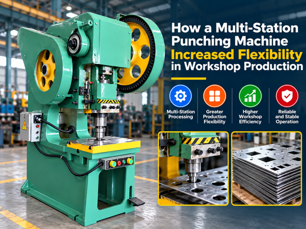
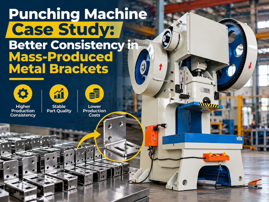
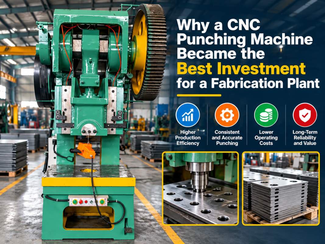
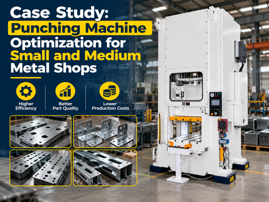
Punching machine tooling is the heart of any metal fabrication operation. At its core, the tooling system consists of a punch, a die, and a stripper. The punch is the male component that penetrates the material, while the die is the female component that provides the opening for the material to be pushed into. The stripper holds the material flat against the die and pulls the punch back out after the stroke. For HARSLE machines, precision in these components is paramount to achieving clean cuts and maintaining high production speeds.
The physics of punching involves more than just brute force. When the punch contacts the sheet metal, it initially compresses the material. As the pressure increases, the material begins to deform plastically, flowing into the die opening. Eventually, the internal stresses exceed the material’s ultimate tensile strength, causing a fracture to start from both the punch and die edges. When these fractures meet, a slug is created and ejected. Understanding this fracture zone is critical for selecting the right tooling geometry.
Material science plays a significant role in tooling performance. Most industrial punches are manufactured from high-speed steels (HSS) or tool steels like D2, M2, or PM-M4. D2 is a high-carbon, high-chromium tool steel known for its excellent wear resistance, making it ideal for long production runs. M2, on the other hand, offers a better balance of toughness and wear resistance, which is preferable for heavy-duty applications where chipping might be a concern. HARSLE recommends selecting tool steel based on the specific tensile strength of the workpiece material.
Modern CNC punching machines utilize turret or linear tool changers. This allows for a variety of shapes—round, square, rectangular, and obround—to be used in a single program. Beyond standard shapes, specialized forming tools like louvers, knockouts, and countersinks can be integrated. The complexity of these tools requires precise alignment and high-quality surface finishes to prevent galling, which is the transfer of material from the workpiece to the tool surface.
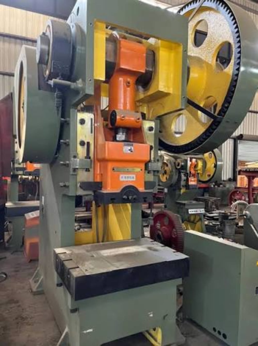
The interaction between the machine’s ram and the tooling is also a technical consideration. Hydraulic and servo-electric punching machines offer different control levels over the punch stroke. A servo-electric HARSLE punch press allows for precise control of the hovering height and the penetration depth, which can significantly extend tool life by reducing unnecessary impact forces. This synergy between hardware and software is what defines modern industrial efficiency.
Core Parameters of Punching Tooling
When discussing Punching Machine Tooling : Types, Selection, Wear Reduction Tips, one must first master the core parameters that dictate the quality of the finished part. The most critical parameter is **Die Clearance**. This is the total difference between the size of the punch and the size of the die. If the clearance is too small, the fractures from the punch and die do not meet, causing secondary shearing and increased tonnage requirements. If it is too large, the material is pulled into the die, resulting in a large burr and excessive rollover.
Another vital parameter is **Shear Angle**. Standard punches are flat-faced, meaning the entire perimeter of the punch contacts the material simultaneously. By adding a shear angle (such as a roof shear or a valley shear) to the punch face, the contact area is reduced, which in turn reduces the required punching force. This is particularly useful when punching thick materials or large holes that might otherwise exceed the machine’s tonnage capacity.
**Tool Geometry** also includes the radius of the corners. In square or rectangular punching, sharp corners are prone to high stress concentrations, which can lead to premature tool failure. Adding a small radius to the corners of the punch can drastically increase its lifespan without significantly affecting the part’s functionality. Furthermore, the **Stripper Force** must be calibrated; insufficient force leads to material warping, while excessive force can mark the sheet surface.
Surface treatments and coatings are the final core parameters to consider. Coatings like Titanium Nitride (TiN) or Titanium Carbonitride (TiCN) provide a hard, lubricious layer that reduces friction and heat buildup. This is especially important when punching stainless steel or aluminum, where galling is a frequent issue. A well-chosen coating can increase the interval between sharpenings by up to 300%.
Calculation Method for Punching Tonnage
Calculating the required tonnage is essential to prevent overloading your HARSLE punching machine and damaging the tooling. The basic formula for calculating punching force (P) is:
P (kN) = L × T × τ / 1000
Where:
L = Perimeter of the hole (mm)
T = Material thickness (mm)
τ = Shear strength of the material (N/mm²)
For a standard round hole, the perimeter (L) is π × Diameter. For a square hole, it is 4 × Side Length. The shear strength (τ) is typically about 70-80% of the material’s ultimate tensile strength. For example, mild steel usually has a shear strength of approximately 345 N/mm², while stainless steel can exceed 500 N/mm².
Let’s look at a practical example. If you are punching a 50mm diameter hole in 3mm thick mild steel:
L = 3.14159 × 50 = 157.08 mm
T = 3 mm
τ = 345 N/mm²
P = (157.08 × 3 × 345) / 1000 = 162.58 kN (approximately 16.5 tons).
If the calculated tonnage is close to the machine’s limit, applying a shear angle to the punch can reduce the peak force by 20% to 50%. It is a best practice to keep the required tonnage below 80% of the machine’s rated capacity to ensure longevity of the hydraulic components and the frame.
Punching Machine Tooling Parameter Table
The following table provides recommended die clearances based on material type and thickness. These percentages represent the *total* clearance (die diameter minus punch diameter).
| Material Type | Thickness Range (mm) | Recommended Total Clearance (% of Thickness) | Expected Burr Height |
|---|---|---|---|
| Mild Steel | 0.5 – 3.0 | 15% – 20% | Low |
| Mild Steel | 3.1 – 6.0 | 20% – 25% | Medium |
| Stainless Steel | 0.5 – 2.0 | 20% – 25% | Medium |
| Stainless Steel | 2.1 – 4.0 | 25% – 30% | High |
| Aluminum (Soft) | 0.5 – 4.0 | 10% – 15% | Low |
| Aluminum (Hard) | 0.5 – 4.0 | 15% – 18% | Low |
| Galvanized Steel | 0.5 – 3.0 | 18% – 22% | Medium |
Common Engineering Mistakes in Tooling Selection
One of the most frequent mistakes in metal punching is using the **wrong die clearance**. Many operators use a “one size fits all” approach, which leads to rapid tool wear. Using a clearance that is too tight for stainless steel, for instance, generates immense heat and can cause the punch to weld itself to the scrap slug. Conversely, too much clearance on thin aluminum will result in the material being “drawn” into the die rather than sheared, creating a messy edge.
Another common error is **neglecting tool alignment**. Even the highest quality HARSLE machine cannot compensate for a misaligned tool holder or a worn turret station. If the punch is not perfectly centered in the die, it will hit one side harder than the other. This causes uneven wear, “shaving” of the die, and can eventually lead to a catastrophic tool breakage. Regular inspection of the alignment keys and bushings is mandatory.
**Improper lubrication** is a silent killer of tooling. Many shops attempt to punch “dry” to avoid cleaning the parts later. However, without lubrication, the friction between the punch and the workpiece increases exponentially. This leads to galling, where small particles of the workpiece stick to the punch. As these particles build up, they increase the effective diameter of the punch, leading to even more friction and eventual tool failure. Using a dedicated punching oil or a mist system is essential for high-volume work.
Finally, **over-sharpening or under-sharpening** tools can be costly. Waiting until the tool produces a massive burr means you have to grind away a significant amount of the tool steel to reach a sharp edge again. On the other hand, sharpening too frequently without removing enough material to get past the heat-affected zone will result in an edge that dulls almost immediately. Using a precision surface grinder with plenty of coolant is the only way to properly maintain these tools.
Selection Checklist for Punching Machine Tooling
- Material Compatibility: Does the tool steel (D2, M2, PM) match the hardness and abrasiveness of the workpiece?
- Tonnage Verification: Have you calculated the required force and ensured it is within 80% of the machine’s capacity?
- Clearance Optimization: Is the die clearance specifically calculated for the material thickness and type?
- Shape and Geometry: Can a shear angle be added to reduce noise and vibration? Are corner radii optimized?
- Coating Requirements: Would a TiCN or CrN coating improve performance for this specific material (e.g., aluminum or stainless)?
- Station Size: Does the tool fit the correct turret station (A, B, C, or D) to ensure maximum stability?
- Slug Management: Does the die feature a “slug hugger” or special geometry to prevent slugs from pulling back up into the machine?
- Lubrication System: Is there an automated mist or manual application plan for punching lubricant?
Wear Reduction Tips for Longevity
To maximize the ROI on your HARSLE punching machine tooling, a proactive maintenance strategy is required. First, implement a **regular sharpening schedule**. Instead of waiting for tool failure, monitor the burr height on your parts. Once the burr exceeds 10% of the material thickness, it is time to sharpen. Removing just 0.1mm to 0.2mm regularly is much better than removing 1.0mm once the tool is completely blunt.
Second, consider **cryogenic treatment** for your tools. This process involves cooling the tool steel to extremely low temperatures to transform retained austenite into martensite, creating a more uniform molecular structure. This can increase wear resistance by up to 50% in certain applications. While it adds an upfront cost, the reduction in downtime and replacement costs is significant.
Third, focus on **slug pulling prevention**. Slug pulling occurs when the scrap piece sticks to the face of the punch and is lifted out of the die. This can cause double-punching, which destroys both the tool and the workpiece. Using dies with specialized internal geometries (like a taper or a small bump) or punches with urethane ejector pins can effectively eliminate this problem.
Lastly, ensure your **stripper plates** are in good condition. The stripper’s job is to hold the material flat. If the stripper is worn or has an opening that is too large, the material will flex during the punch stroke. This flexing causes the punch to enter the material at an angle, leading to side-loading and accelerated wear on the punch guides. Keeping the stripper opening as tight as possible to the punch size provides the best support.
Frequently Asked Questions (FAQ)
1. How often should I sharpen my punching tools?
Sharpening frequency depends on the material being punched. For mild steel, you might get 50,000 to 100,000 hits between sharpenings. For stainless steel, this might drop to 20,000 hits. The best indicator is the burr height on the finished part; when it becomes unacceptable, sharpen the tool immediately.
2. What is the difference between a ‘slug hugger’ die and a standard die?
A standard die has a straight land followed by a taper. A ‘slug hugger’ die has a specialized geometry (often a slight reverse taper or a small protrusion) designed to grip the slug and prevent it from being pulled back up by the punch. This is crucial for preventing machine damage.
3. Can I use the same die for different material thicknesses?
While physically possible, it is not recommended. Each thickness requires a specific clearance to ensure a clean fracture. Using a die with too much clearance for thin material will cause excessive rollover, while too little clearance for thick material will cause secondary shearing and high tonnage.
4. Why is my punch chipping?
Chipping is usually caused by excessive hardness (brittleness) of the tool steel, improper alignment, or punching material that is too hard for the tool grade. Switching to a tougher steel like M2 or reducing the machine speed can often help. Also, check for loose tool holders.
5. Does the punch speed affect tool life?
Yes. High-speed punching generates more heat. If the heat cannot dissipate, it softens the tool edge and leads to rapid dulling. For thick or hard materials, slowing down the ram speed (if your HARSLE machine allows) can significantly extend tool life by reducing thermal stress.
6. What is the best coating for punching aluminum?
For aluminum, a Chromium Nitride (CrN) or a specialized DLC (Diamond-Like Carbon) coating is often best. These coatings have a very low coefficient of friction and prevent the aluminum from “cold welding” to the punch surface, which is the primary cause of failure in aluminum applications.