Punching Machine Setup Guide: Alignment, Calibration, and First-Run Checks


Technical Overview of Punching Machine Systems
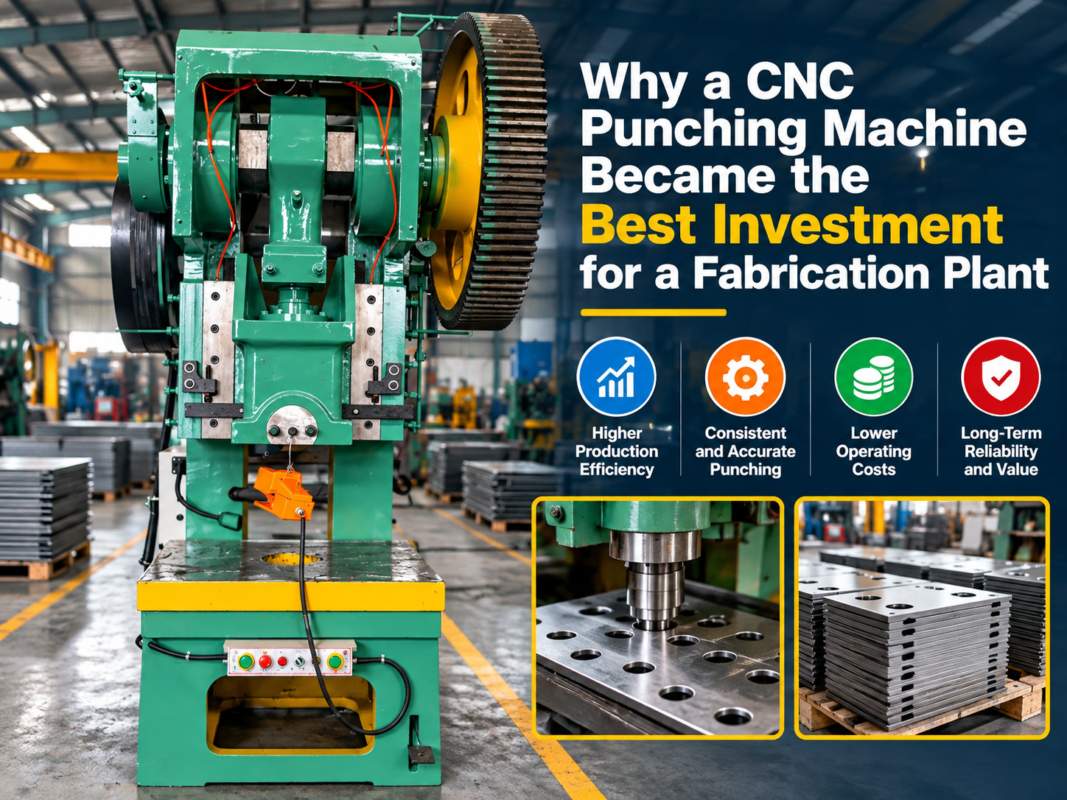
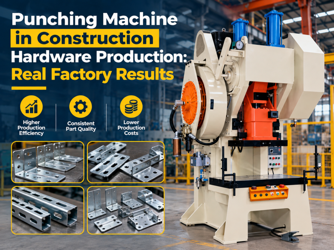
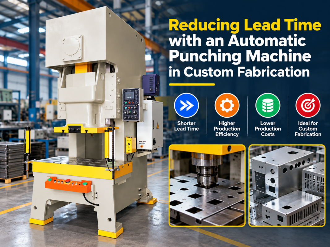
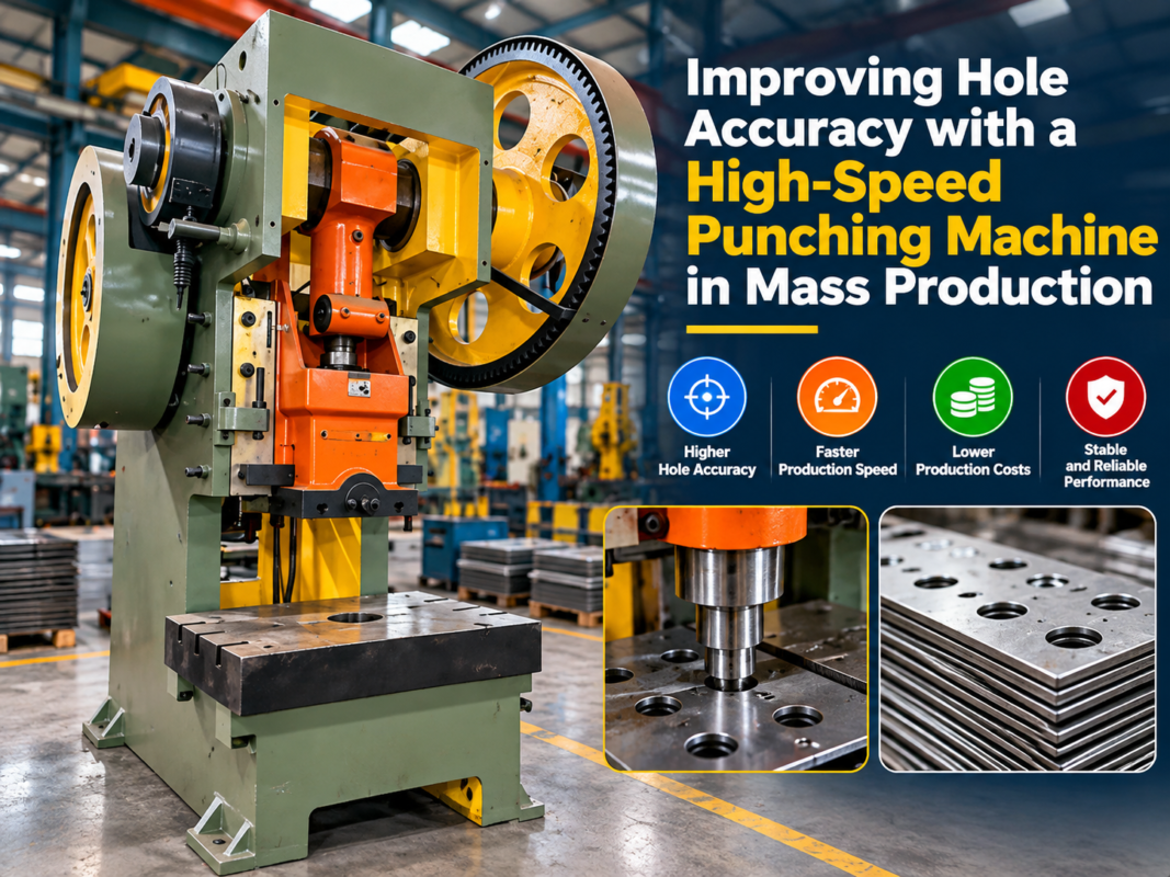
The modern industrial punching machine is a cornerstone of metal fabrication, providing the force and precision necessary to create holes, notches, and forms in sheet metal. Whether you are operating a mechanical flywheel press or a high-tech CNC hydraulic punching machine, the fundamental principles of the Punching Machine Setup : Alignment, Calibration, First-Run Checks remain the same. A proper setup ensures that the machine operates within its designed tolerances, extending the life of both the tooling and the machine frame itself.
At its core, a punching machine consists of a frame (usually C-type or O-type), a drive system (mechanical, hydraulic, or servo-electric), a ram, and a tooling system (punch and die). The alignment of these components is critical. Even a deviation of a few microns can lead to uneven tool wear, burrs on the workpiece, or catastrophic tool failure. HARSLE machines are engineered with high-rigidity frames to minimize deflection, but the operator’s role in initial setup and periodic calibration is what ultimately determines the quality of the output.
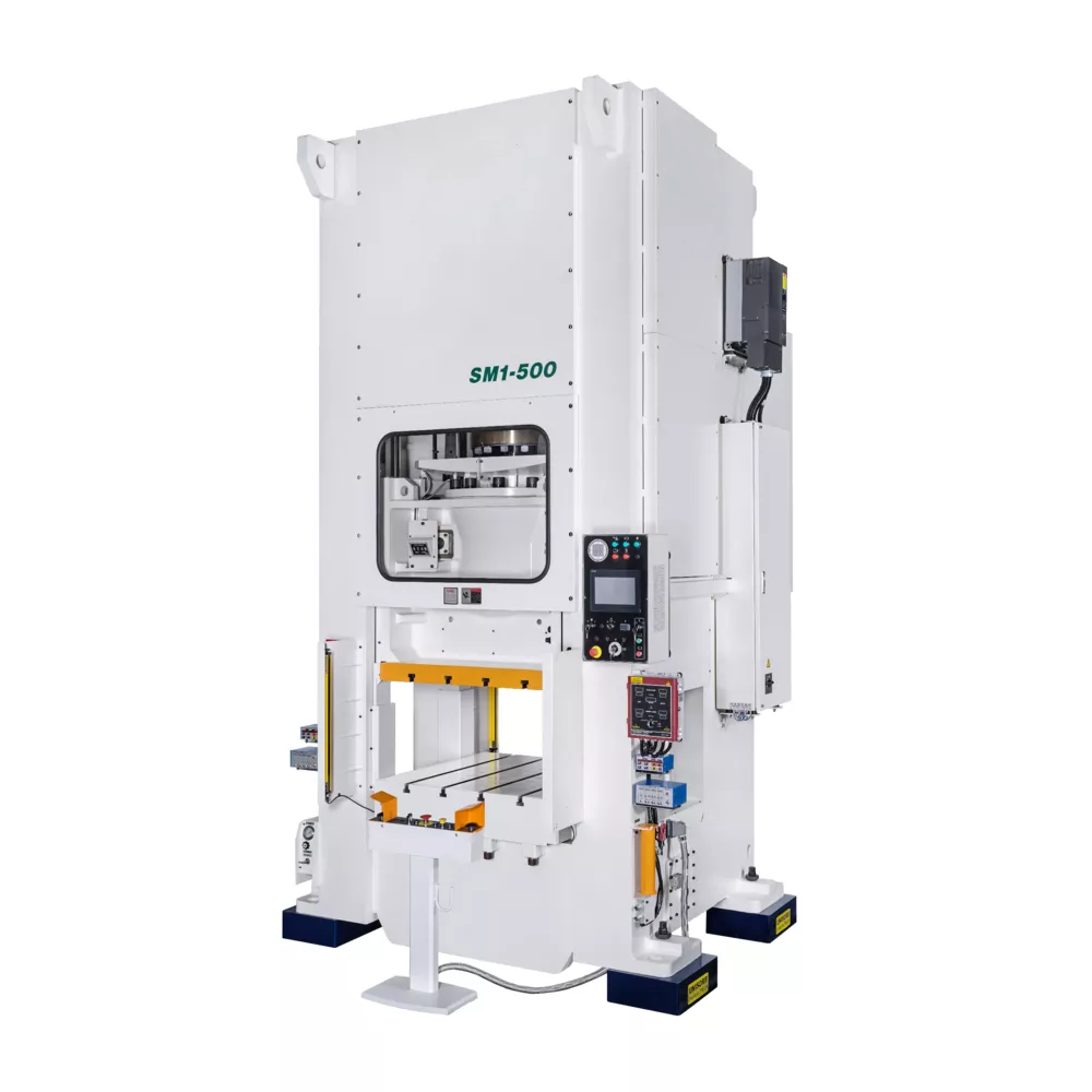
The technical complexity of these machines requires a systematic approach to installation. This involves leveling the machine bed, ensuring the power supply is stable, and verifying that the hydraulic pressure (in hydraulic models) is consistent. For CNC-controlled units, the software integration with the hardware must be seamless, requiring the calibration of the X and Y axes to ensure that the material positioning matches the digital blueprint. This guide provides a deep dive into these processes to ensure your facility maintains peak productivity.
Core Parameters of Punching Machine Operation
Understanding the core parameters is the first step in a successful Punching Machine Setup : Alignment, Calibration, First-Run Checks. The most critical parameter is the Tonnage, which represents the maximum force the machine can exert. Exceeding this limit can cause permanent deformation of the machine frame. Operators must calculate the required force for every job based on material thickness and shear strength.
Another vital parameter is the Stroke Length. In mechanical presses, this is often fixed, while in hydraulic or servo-driven machines, it is adjustable. Proper stroke adjustment ensures that the punch penetrates the die at the correct depth—too shallow, and the slug won’t clear; too deep, and you risk damaging the die or the ram. The ‘Shut Height’ of the machine must also be carefully matched with the tooling height to prevent the ram from bottoming out against the bed.
Speed, measured in Strokes Per Minute (SPM), affects both production rates and heat generation. High-speed punching requires specialized lubrication systems to prevent the punch from overheating and losing its temper. Additionally, the ‘Throat Depth’ determines the maximum width of the sheet metal that can be processed. During setup, these physical constraints must be mapped out to prevent collisions between the material and the machine frame during the feeding process.
Detailed Alignment Procedures
Alignment is perhaps the most meticulous part of the setup. It begins with the centering of the punch and the die. In a turret punching machine, this involves ensuring that the upper turret (holding the punches) and the lower turret (holding the dies) are perfectly synchronized. Any radial or axial misalignment will cause the punch to hit the edge of the die, leading to immediate tool damage. Using alignment pins or optical alignment tools is standard practice for high-precision HARSLE equipment.
The clearance between the punch and the die is another critical alignment factor. This clearance is typically a percentage of the material thickness (usually 15% to 20% for mild steel). If the alignment is off, the clearance becomes uneven—tight on one side and loose on the other. This results in a “heavy burr” on the side with too much clearance and excessive tool wear on the side with too little. During the Punching Machine Setup : Alignment, Calibration, First-Run Checks, operators should use feeler gauges to verify that the clearance is uniform around the entire perimeter of the tool.
Furthermore, the alignment of the backgauge and feeding system is essential for dimensional accuracy. If the feeder is not square to the punching center, every hole will be slightly out of position, leading to cumulative errors across a large sheet. Calibration of the servo motors and the linear guides ensures that the material moves precisely to the programmed coordinates. This involves checking the parallelism of the guide rails and the perpendicularity of the X and Y axes using precision squares and dial indicators.
Calibration of Hydraulic and Electronic Systems
Calibration goes beyond physical alignment; it involves the fine-tuning of the machine’s internal systems. For hydraulic punching machines, pressure calibration is paramount. The relief valves must be set to the correct pressure to ensure the machine delivers its rated tonnage without over-pressurizing the cylinders. This is done using a calibrated pressure gauge and a load cell to verify that the actual force at the ram matches the readout on the control panel.
In CNC systems, the calibration of the ‘Zero Point’ or ‘Home Position’ is the foundation of all subsequent operations. The machine must know exactly where the ram and the table are located in physical space. This is achieved through the use of limit switches and encoders. During setup, the operator must verify that the machine returns to the exact same home position every time. Any drift in this position indicates a mechanical looseness or an electronic fault that must be addressed before production begins.
Software calibration also includes the ‘Tool Library’ setup. Each tool’s dimensions, including its height, diameter, and wear compensation factors, must be entered into the CNC system. If the software thinks a tool is 100mm long when it is actually 102mm, the ram will travel too far, potentially causing a crash. Regular calibration of these digital parameters ensures that the physical reality of the machine matches the virtual model in the controller.
Calculation Method for Punching Force
To ensure a safe Punching Machine Setup : Alignment, Calibration, First-Run Checks, one must accurately calculate the punching force required for the specific material and geometry. The standard formula for calculating the punching force (P) in kilonewtons (kN) is:
P = L × t × τ / 1000
- L: The perimeter of the hole (mm). For a round hole, L = π × d. For a square hole, L = 4 × side.
- t: The thickness of the material (mm).
- τ: The shear strength of the material (N/mm²). For mild steel, this is typically around 400 N/mm²; for stainless steel, it can be 600 N/mm² or higher.
For example, if you are punching a 50mm diameter hole in 3mm thick mild steel:
L = 3.14159 × 50 = 157.08 mm
P = 157.08 × 3 × 400 / 1000 = 188.5 kN (approximately 19 tons).
It is a best practice to add a 20% safety margin to this calculation to account for tool dulling and material variations. Therefore, a machine with at least 25 tons of capacity would be recommended for this specific task. Understanding this calculation prevents overloading the machine during the first-run checks.
Punching Machine Parameter Table
The following table provides a reference for standard parameters across different classes of HARSLE punching machines. These values are typical for high-quality industrial equipment and should be used as a guideline during the selection and setup phase.
| Machine Model (Tonnage) | Max Thickness (Mild Steel) | Stroke Length (Adjustable) | Strokes Per Minute (SPM) | Motor Power (kW) | Throat Depth (mm) |
|---|---|---|---|---|---|
| 16T | 3.0 mm | 20-60 mm | 120 | 2.2 | 200 |
| 25T | 4.5 mm | 30-80 mm | 100 | 3.0 | 250 |
| 40T | 6.0 mm | 40-100 mm | 80 | 4.0 | 300 |
| 63T | 8.0 mm | 50-120 mm | 70 | 5.5 | 400 |
| 100T | 10.0 mm | 60-150 mm | 55 | 7.5 | 500 |
Common Engineering Mistakes During Setup
One of the most frequent mistakes in Punching Machine Setup : Alignment, Calibration, First-Run Checks is neglecting the foundation. A punching machine generates significant vibration and shock loads. If the machine is not bolted to a reinforced concrete pad or if the leveling pads are not properly adjusted, the machine will “walk” or tilt over time. This leads to misalignment of the internal components and premature wear of the bearings and bushings.
Another common error is the incorrect installation of the die. If the die is not seated perfectly flat in the die holder, it will tilt under pressure. This causes the punch to enter the die at an angle, leading to “shaving” of the die walls and potential breakage of the punch tip. Operators often rush this step, but a few extra minutes spent cleaning the die seat and ensuring a flush fit can save thousands of dollars in tooling costs.
Inadequate lubrication is a silent killer of punching machines. Many operators assume that the automatic lubrication system is working without actually verifying the flow of oil to the ram guides and the crankshaft. During the first-run checks, it is vital to manually trigger the lubrication cycle and ensure that oil is reaching all critical friction points. Running a machine “dry” for even a few hours during the break-in period can cause permanent scoring of the precision-ground surfaces.
Finally, ignoring the material’s grain direction can lead to unexpected results. Metal has different properties depending on whether it is punched with or against the grain. While this is more critical in bending, in punching, it can affect the way the slug breaks away and the amount of “pull-down” or deformation around the hole. A professional setup includes testing the material properties and adjusting the clearance accordingly.
Selection Checklist for Punching Equipment
When selecting a new punching machine or evaluating an existing one during a setup overhaul, use the following checklist to ensure all technical requirements are met:
- Tonnage Capacity: Does the machine have at least 20% more capacity than your thickest/hardest material requires?
- Frame Rigidity: Is the frame designed to minimize angular deflection (yawning) under full load?
- Tooling Compatibility: Does the machine use standard tooling (like Amada or Trumpf style) that is easily sourced and replaced?
- Control System: Is the CNC interface intuitive, and does it support the file formats (DXF/DWG) used by your design team?
- Safety Features: Are light curtains, emergency stops, and interlocked guards fully functional and compliant with local regulations?
- Maintenance Access: Are the lubrication points and hydraulic filters easily accessible for routine servicing?
- Expansion Capability: Can the machine be upgraded with auto-index stations or sheet loaders in the future?
- Manufacturer Support: Does the brand (like HARSLE) provide comprehensive technical manuals and readily available spare parts?
First-Run Checks: A Step-by-Step Protocol
The first-run check is the final validation of the Punching Machine Setup : Alignment, Calibration, First-Run Checks. Before turning on the power, perform a visual inspection of all bolts, hydraulic hoses, and electrical connections. Ensure that the work area is clear of tools and debris. Once the machine is powered on, start with a “Dry Run”—operating the machine through its full cycle without any material or tooling installed. This allows you to listen for unusual noises, such as grinding or knocking, which could indicate mechanical interference.
Next, install the tooling and perform a “Jog” test. Move the ram down slowly in manual mode to verify that the punch enters the die smoothly and that the clearance is even. Once satisfied, perform a single punch on a scrap piece of the intended material. Inspect the resulting hole. A perfect punch will have a clean “shear” zone for the top third of the thickness and a consistent “break” zone for the bottom two-thirds. If the break is uneven, re-check the alignment.
Finally, run a small batch of parts at production speed. Monitor the temperature of the hydraulic oil and the motor. Check the dimensional accuracy of the parts against the drawing. If the machine is a CNC model, verify that the hole patterns are correctly positioned relative to the sheet edges. Only after these checks are successfully completed should the machine be cleared for full-scale production. Documenting these results provides a baseline for future maintenance and calibration cycles.
Frequently Asked Questions (FAQ)
1. How often should I calibrate my punching machine?
For high-volume production, a basic alignment check should be performed weekly. A full system calibration, including hydraulic pressure and CNC axis accuracy, should be conducted every six months or after any major mechanical repair.
2. Why is my punch breaking frequently?
The most common causes are misalignment between the punch and die, insufficient clearance for the material thickness, or using a punch that is too small for the material thickness (the diameter of the punch should generally be at least equal to the material thickness).
3. Can I punch stainless steel on a machine rated for mild steel?
Yes, but you must reduce the maximum thickness. Stainless steel is much harder and has a higher shear strength. You must recalculate the required tonnage using the shear strength of the specific grade of stainless steel to ensure you don’t exceed the machine’s capacity.
4. What is the purpose of ‘shear’ on a punch?
Adding an angle (shear) to the face of the punch reduces the initial impact force and the total tonnage required for the hole. It allows a lower-capacity machine to punch larger holes, though it may cause slight distortion in the slug or the workpiece.
5. How do I know if my die clearance is correct?
Examine the slug. If the clearance is correct, the slug will have a uniform appearance. If the clearance is too tight, you will see a secondary shear (a double-shiny band). If it is too loose, you will see a large, jagged burr and a significant roll-over at the top of the hole.