A Technical Guide to Punching Machine Die Sets and Punch Tool Design

Technical Overview of Punching Machine Die Sets
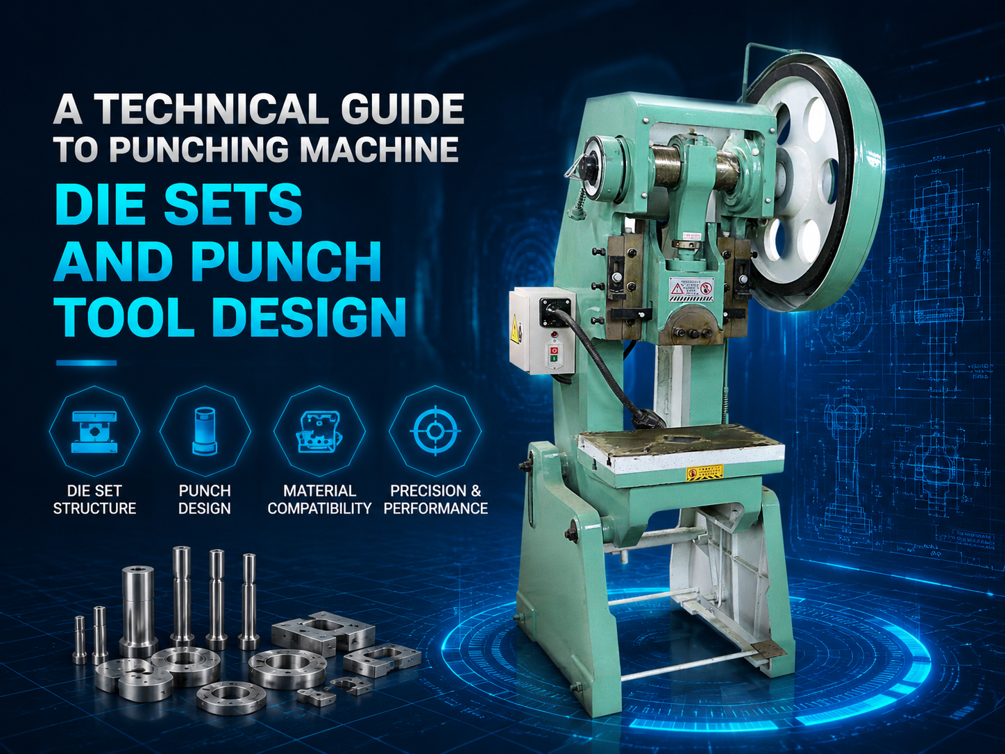
In the realm of modern metal fabrication, the efficiency and precision of a punching operation are fundamentally dictated by the quality and design of the die set. A Technical Punching Machine Die Sets Punch Tool Design involves a complex interplay of mechanical engineering, material science, and precision manufacturing. At HARSLE, we recognize that the die set is not merely a holder for tools but the heart of the punching process, ensuring that the punch and die maintain perfect alignment under immense pressure.
A standard die set consists of several critical components: the upper shoe (punch holder), the lower shoe (die holder), guide pins, and bushings. The upper shoe is attached to the ram of the punching machine, while the lower shoe is secured to the bolster plate. The guide pins and bushings are perhaps the most vital elements, as they ensure that the punch enters the die with microscopic accuracy. Any deviation in this alignment can lead to premature tool wear, burrs on the workpiece, or even catastrophic tool failure.
The evolution of A Technical Punching Machine Die Sets Punch Tool Design has seen a shift from simple manual setups to sophisticated, multi-station turret systems and CNC-controlled hydraulic presses. Modern die sets are designed to handle high-speed operations, often exceeding hundreds of strokes per minute. This requires materials that can withstand thermal expansion and high-cycle fatigue. Common materials for the die set base include high-tensile cast iron or steel plate, which provide the necessary rigidity to resist deflection during the punching stroke.
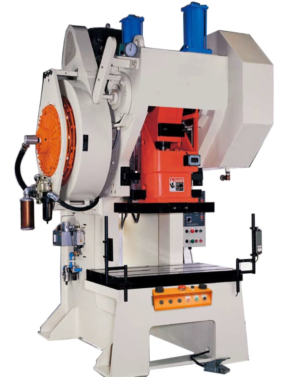
Furthermore, the design must account for slug management. As the punch penetrates the material, the resulting slug must be efficiently ejected through the die. Failure to manage slug evacuation can lead to ‘slug pulling,’ where the waste material sticks to the punch and is pulled back up, potentially damaging the next workpiece or the tool itself. Advanced die designs often incorporate vacuum systems or specialized die geometries to mitigate this risk.
Core Parameters in Punch Tool Design
When discussing A Technical Punching Machine Die Sets Punch Tool Design, several core parameters must be meticulously defined to ensure optimal performance. The most critical of these is ‘Clearance.’ Clearance is the intentional gap between the punch diameter and the die diameter. It is usually expressed as a percentage of the material thickness. Correct clearance ensures a clean fracture in the material, resulting in a hole with minimal burr and a smooth edge. If the clearance is too tight, it increases the force required and accelerates tool wear; if it is too loose, it results in excessive burrs and material deformation.
Another essential parameter is the ‘Shear Angle.’ To reduce the peak tonnage required for a punching operation, the face of the punch or the die can be ground at an angle. This ‘shear’ allows the tool to enter the material gradually rather than all at once. This is particularly useful when punching thick materials or large diameters that might otherwise exceed the machine’s rated capacity. However, adding a shear angle can introduce lateral forces, which must be compensated for in the die set design to prevent misalignment.
The ‘Stripper Force’ is also a vital consideration. After the punch has penetrated the material, it must be withdrawn. Because the material tends to grip the punch due to elastic recovery, a stripper plate is used to hold the material down while the punch retracts. The design of the stripper—whether it is a fixed plate or a spring-loaded pressure plate—depends on the material thickness and the required surface finish of the part. In high-precision applications, a guided stripper is often used to provide additional support to the punch, reducing the risk of deflection.
Finally, the choice of tool steel is paramount. For A Technical Punching Machine Die Sets Punch Tool Design, engineers typically choose between water-hardening (W-series), oil-hardening (O-series), air-hardening (A-series), or high-speed steels (M-series). D2 tool steel is a popular choice for its excellent wear resistance and toughness, making it ideal for long production runs. For heavy-duty applications involving stainless steel or high-strength alloys, M2 or powdered metal (PM) steels are often preferred due to their superior red-hardness and impact resistance.
Calculation Method for Punching Force and Clearance
To achieve success in A Technical Punching Machine Die Sets Punch Tool Design, precise mathematical calculations are required. The most fundamental calculation is determining the punching force (tonnage). The formula for calculating the required force (P) is:
P = L × t × τ
Where:
– P is the punching force (in Newtons or Tons).
– L is the perimeter of the hole (for a round hole, L = π × d).
– t is the material thickness.
– τ is the shear strength of the material (usually about 80% of the tensile strength).
It is standard engineering practice to add a 20-30% safety factor to this calculated value to account for tool dulling and variations in material properties. If the calculated tonnage exceeds the machine’s capacity, designers must implement a shear angle on the punch to distribute the load over a longer stroke length.
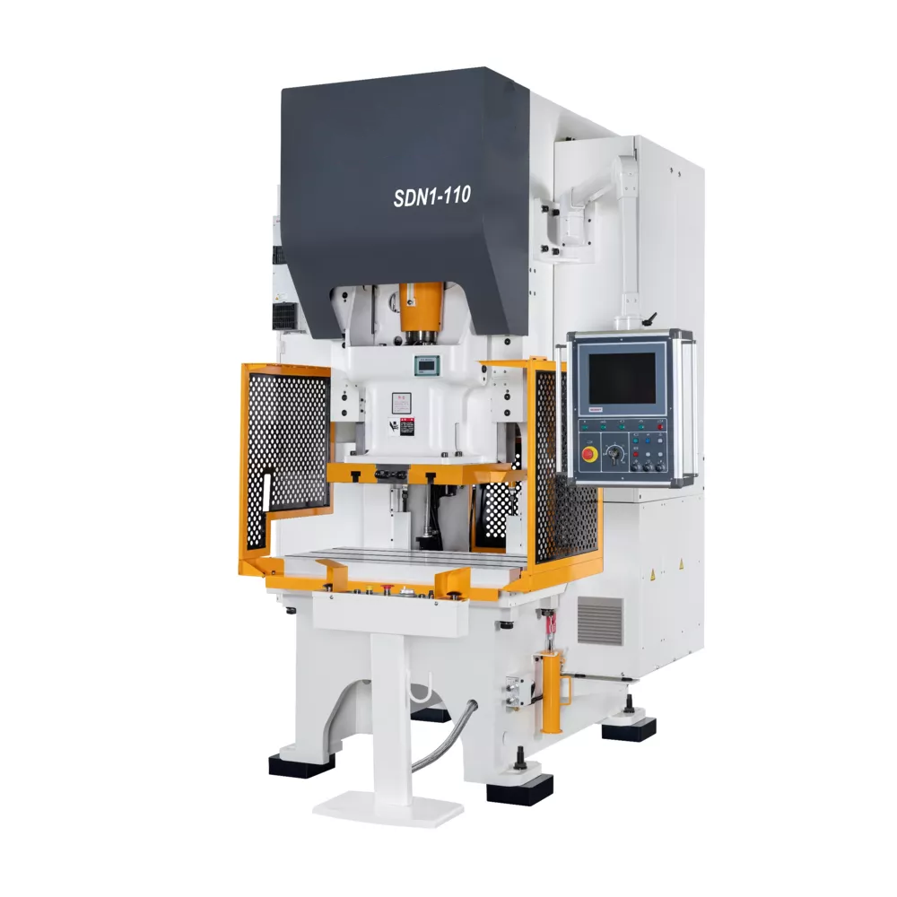
The calculation of clearance (c) is equally important. While a general rule of thumb is 5% to 10% of the material thickness per side, specific materials require different approaches. For example, aluminum may require a tighter clearance (approx. 5%) to prevent ‘shaving,’ while high-carbon steel might require 10-15% to facilitate a clean fracture. The formula is generally expressed as:
c = a × t
where ‘a’ is a coefficient based on the material type and ‘t’ is the thickness.
Stripping force is another calculation that shouldn’t be overlooked. Typically, the stripping force is estimated at 10% to 20% of the punching force. This ensures that the springs or hydraulic cylinders in the stripper plate have enough energy to overcome the friction between the punch and the material during the return stroke. Inadequate stripping force is a leading cause of ‘slug pulling’ and machine downtime.
Parameter Table for Tooling Selection
The following table provides a technical reference for clearance and material selection in A Technical Punching Machine Die Sets Punch Tool Design. These values are intended as a baseline for standard industrial applications.
| Material Type | Tensile Strength (MPa) | Recommended Clearance (% of t) | Recommended Tool Steel | Lubrication Requirement |
|---|---|---|---|---|
| Aluminum (Soft) | 70 – 150 | 3% – 5% | A2 / D2 | Low to Medium |
| Mild Steel (CR) | 340 – 450 | 8% – 10% | D2 / M2 | Medium |
| Stainless Steel (304) | 515 – 620 | 12% – 15% | M2 / PM-M4 | High (EP Additives) |
| High Carbon Steel | 600 – 900 | 12% – 18% | CPM 10V | High |
| Copper / Brass | 200 – 400 | 4% – 6% | O1 / A2 | Low |
Note: The ‘Clearance’ values above refer to the total clearance (the difference between die diameter and punch diameter). For per-side clearance, divide these values by two. Always consult with HARSLE technical support when working with exotic alloys or extreme thicknesses.
Common Engineering Mistakes in Die Design
Even with advanced software, errors in A Technical Punching Machine Die Sets Punch Tool Design can occur. One of the most frequent mistakes is ignoring the ‘Die Land.’ The die land is the straight portion of the die opening before it tapers off for slug clearance. If the land is too long, slugs can jam due to friction; if it is too short, the die may lose its structural integrity and chip under load. A typical die land is 3mm to 6mm, depending on the material thickness.
Another common error is improper heat treatment of the punch and die. While it is tempting to maximize hardness (HRC), a tool that is too hard becomes brittle and prone to cracking under shock loads. Conversely, a tool that is too soft will deform and lose its edge quickly. Achieving the right balance of hardness and toughness through controlled tempering is essential for tool longevity. For D2 steel, a hardness of 58-60 HRC is generally optimal for punching applications.
Neglecting lubrication is a third major mistake. In high-speed punching, the friction between the punch and the workpiece generates significant heat. Without proper lubrication, the material can ‘gall’ or weld itself to the punch surface. This not only ruins the workpiece finish but also increases the stripping force required, leading to potential tool breakage. Automated mist lubrication systems are highly recommended for CNC punching machines to ensure consistent application.
Finally, many engineers fail to account for the ‘Punch Radius.’ Sharp corners on a rectangular or square punch are stress concentrators. Adding a small radius (even 0.1mm to 0.2mm) to the corners of the punch can significantly increase the tool’s resistance to chipping without affecting the part’s functionality. This is a subtle but crucial aspect of A Technical Punching Machine Die Sets Punch Tool Design that separates high-quality tooling from budget alternatives.
Selection Checklist for Punching Machine Die Sets
When selecting or designing a die set for your HARSLE punching machine, use the following checklist to ensure all technical requirements are met:
- Material Compatibility: Does the tool steel match the hardness and abrasiveness of the workpiece material?
- Tonnage Capacity: Is the calculated punching force within 70% of the machine’s rated capacity?
- Clearance Optimization: Has the clearance been adjusted for the specific thickness and shear strength of the material?
- Slug Management: Does the die design include a proper taper or vacuum system to prevent slug pulling?
- Alignment System: Are the guide pins and bushings rated for the required precision and stroke speed?
- Coating Requirements: Would a TiN (Titanium Nitride) or TiAlN coating extend tool life for this specific application?
- Maintenance Accessibility: Can the punch and die be easily removed for sharpening without dismantling the entire die set?
- Lubrication Strategy: Is there a provision for consistent lubrication of the punch point and the stripper?
Frequently Asked Questions (FAQ)
1. How often should I sharpen my punch and die?
Sharpening frequency depends on the material being punched and the tool steel used. A general rule is to sharpen the tool when the burr height on the workpiece exceeds 10% of the material thickness. Regular, light sharpening (removing 0.1mm to 0.2mm) is much better for tool life than waiting until the tool is severely rounded.
2. What causes ‘Slug Pulling’ and how can I stop it?
Slug pulling occurs when the waste material sticks to the face of the punch. This can be caused by excessive lubrication, vacuum effect, or magnetized tools. Solutions include using ‘slug-hugger’ die geometries, installing urethane ejector pins in the punch, or using a vacuum slug removal system.
3. Can I punch holes smaller than the material thickness?
Technically, it is possible, but it is extremely hard on the tooling. The ‘1-to-1 rule’ suggests that the hole diameter should be at least equal to the material thickness. For holes smaller than the thickness, you must use high-strength PM steels, guided strippers, and very precise clearances to prevent punch breakage.
4. Why is my punch chipping on the edges?
Chipping is usually a sign of excessive hardness, misalignment, or insufficient clearance. If the punch is hitting the die due to guide pin wear, it will chip. Similarly, if the clearance is too tight for the material’s tensile strength, the lateral forces can cause the edges to fail. Check your alignment and consider a slightly larger clearance.
5. What is the benefit of using a coated punch?
Coatings like TiN or DLC (Diamond-Like Carbon) reduce friction and increase surface hardness. This is particularly beneficial when punching ‘gally’ materials like aluminum or stainless steel. Coatings can increase tool life by 3 to 10 times in the right applications by preventing material pick-up and reducing heat generation.
By following this technical guide to A Technical Punching Machine Die Sets Punch Tool Design, manufacturers can significantly improve their production efficiency, reduce tool replacement costs, and ensure the highest quality for their fabricated parts. HARSLE remains committed to providing the industry with the machinery and knowledge necessary to excel in the competitive field of metal fabrication.