High-Precision Hydraulic Control with Proportional Valves

In modern industrial automation, precision and repeatability in sheet metal fabrication are more critical than ever. At the core of this precision is the ability to accurately control hydraulic power. Proportional valves serve as the key link between electronic control systems and hydraulic actuators. Unlike traditional on-off valves, they allow continuous adjustment of flow and pressure. This makes them essential for CNC press brakes and high-speed shearing machines, where even small deviations affect final quality. By converting low-power electrical signals into controlled hydraulic output, proportional valves enable complex and precise motion control. Understanding their function helps engineers improve accuracy, efficiency, and machine reliability.
Understanding the Basics of Proportional Valves
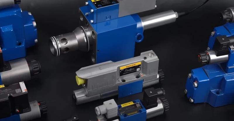
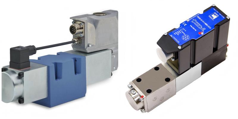
A proportional valve is a hydraulic component that adjusts output—pressure or flow—in direct proportion to an electrical input signal. Its core structure includes an electromagnetic solenoid acting on a spool. Unlike standard solenoids with fixed positions, proportional solenoids vary force based on input current. This force balances against a spring, allowing the spool to move to any position within its stroke range. The spool position controls the size of the flow orifice, directly regulating actuator speed or force. In high-precision systems, an LVDT (Linear Variable Differential Transformer) provides real-time position feedback, ensuring the spool position precisely matches the control signal for accurate and stable operation.
The transition from discrete to proportional control represents the single greatest leap in hydraulic efficiency and machine versatility in the last thirty years.
Why Proportional Valves Matter in Sheet Metal Fabrication
In CNC bending, precise synchronization of hydraulic cylinders is crucial for achieving consistent 90-degree bends across long workpieces. Proportional valves enable real-time micro-adjustments to compensate for material thickness variations or off-center loading. Without this fine control, machines would experience jerky movements, excessive vibration, and poor repeatability. Proportional technology also allows for controlled deceleration ramps, preventing hydraulic shocks and extending the service life of seals, pumps, and piping. This results in lower maintenance costs and increased factory throughput, making proportional valves an essential component in optimizing performance and reducing operational downtime in sheet metal fabrication.
Key Factors to Consider for Proportional Valves
When specifying or troubleshooting proportional valves in a fabrication environment, key factors must be assessed to ensure optimal performance. First, hysteresis is the variation in output for the same input signal based on whether the signal is increasing or decreasing. High-quality valves typically aim for hysteresis below 1 percent. Next, frequency response measures how quickly the valve can react to control signal changes, which is vital for high-speed applications like laser cutting or punch presses. The deadband refers to the range around the spool’s center position where movement is required before flow starts. Modern digital amplifiers can compensate electronically for deadband, but spool design—whether zero-lap or slight overlap—remains critical for hydraulic system stability.
Technical Principles of Proportional Valve Control
The control of proportional valves is based on electromagnetism and fluid dynamics. Engineers calculate flow using the formula: Q = Cd * A * sqrt( (2 * ΔP) / ρ ), where Q is the flow rate, Cd is the discharge coefficient (typically 0.6 to 0.65), A is the variable opening area, ΔP is the pressure drop, and ρ is fluid density. The electrical signal adjusts A, controlling flow. Pulse Width Modulation (PWM) regulates the solenoid by switching full voltage on and off at a high frequency. The duty cycle determines the average current and solenoid force. ‘Dither’, a high-frequency oscillation, prevents the valve from sticking due to static friction.
| Technical Parameter | Standard Proportional Valve | High-Performance (with Feedback) |
|---|---|---|
| Hysteresis | 3 percent to 5 percent | Less than 0.5 percent |
| Frequency Response | 10 Hz to 20 Hz | Up to 100 Hz |
| Repeatability | Moderate | Very High |
| Contamination Tolerance | ISO 4406 18/16/13 | ISO 4406 16/14/11 |
Comparison of Proportional Valves vs. Servo Valves
While both technologies provide variable control, they serve different niches in the industrial sector. Servo valves generally utilize a mechanical feedback system (like a flapper-nozzle or jet pipe) and offer the highest level of dynamic response and precision. However, they are extremely sensitive to fluid contamination and are significantly more expensive. Proportional valves, especially those with integrated electronics and spool position feedback, have closed the performance gap significantly. For most sheet metal applications, such as large tonnage press brakes or plate rollers, the proportional valve offers the best balance of cost-effectiveness, durability, and precision. The following table highlights the primary differences for procurement and engineering teams.
| Feature | Proportional Valve | Servo Valve |
|---|---|---|
| Spool Drive | Direct Solenoid | Pilot Stage (Flapper/Jet) |
| Power Requirement | Higher Solenoid Current | Low Signal Current |
| Failure Mode | Spring Centered (Safe) | Variable depending on design |
| Maintenance | Standard Hydraulic Care | Specialized Clean-Room Service |
Step-by-Step Implementation Guide
Integrating a proportional valve into a hydraulic system requires a systematic approach. Step 1: Define the required flow and pressure drop based on actuator size and speed. Step 2: Select a valve with an appropriate flow rating; oversizing can cause instability and poor performance at low speeds. Step 3: Choose the correct electronic driver or amplifier, ensuring it provides the required peak current and has gain, ramp time, and dither adjustments. Step 4: Implement a filtration system with at least a 10-micron absolute filter to prevent particulate contamination. Step 5: Commission the system, adjusting null point and gain under load conditions, ensuring tests are done at the machine’s operating temperature.
Common Mistakes in Hydraulic System Integration
A common error engineers make is neglecting the thermal management of hydraulic fluid. As oil temperature rises, viscosity drops, leading to increased internal leakage and altered valve performance. Another mistake is inadequate electrical shielding. Proportional valves, which operate on variable signals, are susceptible to Electromagnetic Interference (EMI) from nearby high-power equipment like motor drives and welders. Using unshielded cables can cause ‘hunting’ or unstable actuator movement. Lastly, improper sizing of the pilot supply is a frequent issue. If system pressure drops too low during high-demand cycles, the valve may lack sufficient pilot pressure to shift the spool correctly, resulting in sluggish performance or system failure.
In high-precision hydraulics, the cleanliness of the fluid is not just a maintenance task; it is a fundamental design requirement.
Industry Applications in Press Brakes and Cutting
Proportional valves play a crucial role in the sheet metal industry, particularly in CNC press brakes. They control the synchronization of dual hydraulic rams, ensuring perfect leveling within microns during the bending stroke. In CNC shearing machines, proportional control automatically adjusts the blade gap and rake angle based on material thickness, ensuring clean cuts without burrs. In deep-drawing hydraulic presses, these valves regulate the blank holder pressure during the draw cycle, preventing metal wrinkling or tearing by adjusting clamping force in real-time. These applications highlight how proportional valves control the physics of metal deformation, going beyond simple motion to achieve precise, high-quality results.
Conclusion
Proportional valves are the unsung heroes of modern sheet metal fabrication. They provide the necessary bridge between digital logic and physical force, enabling the high levels of precision, speed, and reliability that today’s market demands. By understanding the technical principles of spool positioning, the importance of electronic feedback, and the necessity of fluid cleanliness, manufacturers can ensure their equipment operates at peak efficiency. For those investing in new machinery, prioritizing high-quality proportional control systems is a strategic decision that pays dividends in reduced waste, higher part quality, and lower long-term maintenance costs. As the industry moves toward further automation and Industry 4.0 integration, the role of these precision components will only become more vital.
FAQ
What is the difference between a proportional valve and a standard directional valve?
A standard directional valve is binary, meaning it is either fully open or fully closed. A proportional valve can be positioned at any increment between these states, allowing for variable control of speed and pressure.
How does an LVDT improve proportional valve performance?
An LVDT provides electronic feedback of the actual spool position to the controller. This allows the system to correct for any mechanical resistance or friction, ensuring the spool reaches the exact position commanded by the software.
What is ‘dither’ and why is it used?
Dither is a low-amplitude, high-frequency electrical vibration applied to the solenoid. It keeps the valve spool in constant micro-motion, which prevents static friction (stiction) and improves the valve’s response to small signal changes.
Can proportional valves be used for position control?
Yes, when paired with a linear encoder on the hydraulic cylinder and a closed-loop CNC controller, proportional valves can achieve highly accurate position control, which is essential for bending and punching operations.
What level of oil filtration is required for these valves?
Proportional valves generally require high levels of fluid cleanliness, typically rated at ISO 4406 17/15/12 or better. Using a 10-micron absolute filter is standard practice to prevent spool jamming and erosion.


