Pneumatic Press Brakes: When Are They Suitable for Production?


In the evolving landscape of sheet metal fabrication, selecting the appropriate bending technology is a critical decision that impacts throughput, precision, and operational costs. While hydraulic and electric servo-driven machines dominate the high-tonnage and high-precision markets, pneumatic press brakes have carved out a significant niche in the manufacturing of light-gauge components. These machines utilize compressed air as their primary power source, offering a distinct set of mechanical characteristics that differ fundamentally from their oil-dependent counterparts. For engineering managers and shop floor owners, understanding the technical boundaries and advantages of pneumatic press brakes is essential for optimizing production lines where speed and simplicity are paramount.
Understanding the Basics of Pneumatic Press Brakes
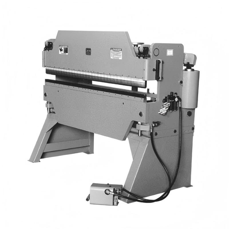
A pneumatic press brake is a sheet metal bending machine that uses compressed air to drive its ram, contrasting with hydraulic systems that rely on fluid pressure. These machines typically employ multiple high-capacity air cylinders, often paired with a toggle linkage to amplify force as the ram reaches the stroke’s end. The design is straightforward, with fewer seals, no oil reservoirs, and no hydraulic pumps, making the system cleaner and easier to maintain. Pneumatic press brakes operate faster than their hydraulic counterparts but are limited in maximum tonnage, generally handling 1–30 tons. They are ideal for bending thinner materials, usually under 2 mm, offering an efficient, low-maintenance solution for light-duty sheet metal work.
In high-volume, light-gauge fabrication, the cycle speed of a pneumatic press brake can often exceed that of a hydraulic machine by 30 percent or more, provided the tonnage requirements remain within the pneumatic threshold.
Why This Topic Matters in Sheet Metal Fabrication
Pneumatic technology has become highly relevant in modern fabrication due to its impact on Total Cost of Ownership (TCO) and support for lean manufacturing. Unlike hydraulic systems, pneumatic press brakes eliminate energy-intensive oil heating and cooling, reducing environmental impact and risk of fluid leaks. Their fast cycle times suit cell-based production, efficiently handling small parts and moving them quickly between stations. For facilities producing electronics enclosures, HVAC components, or medical device brackets, investing in large hydraulic machines often wastes floor space and energy. Pneumatic systems provide a cost-effective, space-efficient alternative. Recognizing the applications where pneumatic presses excel—balancing speed, efficiency, and energy savings—is a key strategy for optimizing production and achieving high operational efficiency.
Key Factors to Consider for Pneumatic Press Brakes
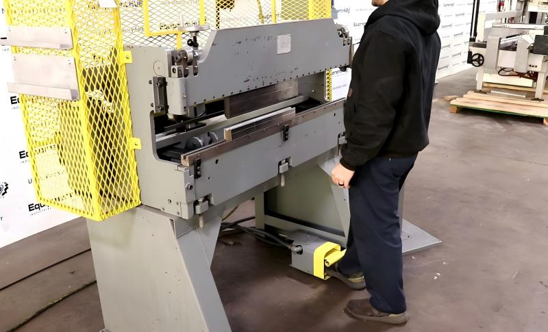
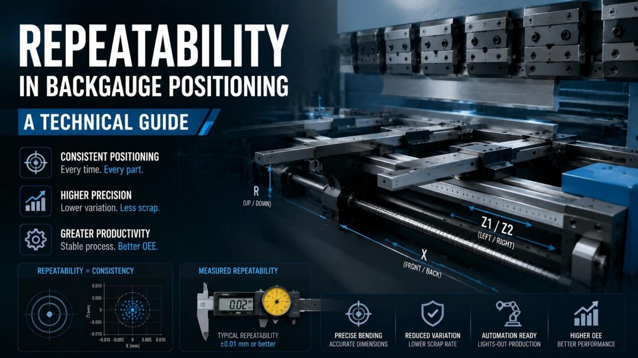
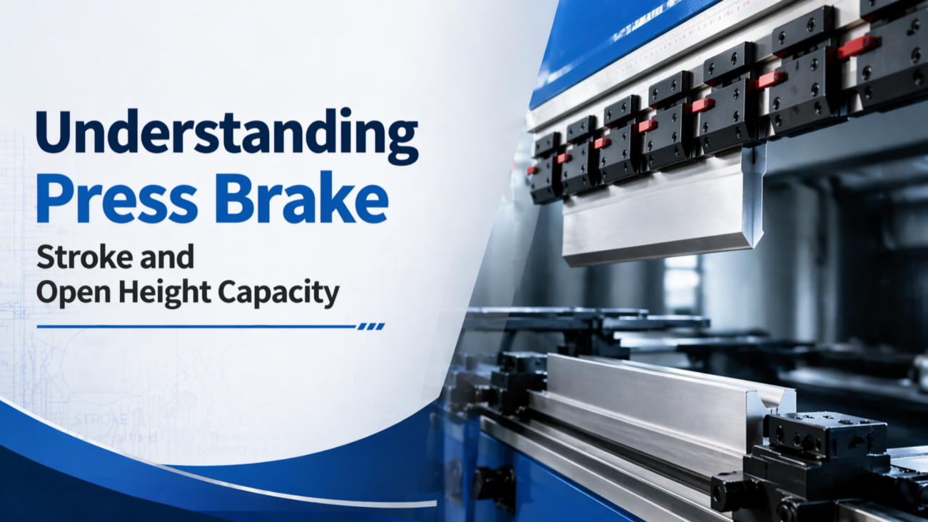
When selecting a pneumatic press brake for production, several technical factors are critical. Material thickness and tensile strength determine the required force, and because air is compressible, the cylinder’s force curve is nonlinear. Manufacturers address this with mechanical linkages that maximize force at the point of contact. Air quality is essential, as moisture or particulates can damage solenoid valves and cylinder seals, so filtration and drying systems are necessary. The backgauge must operate at high speed to keep pace with the ram; a slow backgauge negates productivity benefits. Finally, stroke length and open height should be considered, as pneumatic machines generally have shorter strokes than hydraulics, limiting their ability to perform deep-box or complex bends efficiently.
Technical Explanation of Pneumatic Press Brakes Force
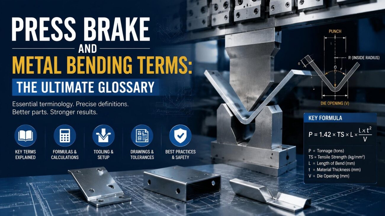
Calculating bending force is key when evaluating a pneumatic press brake. For V-bends, the standard formula is F = [k × L × UTS × t²] / [W × 1000], where F is force in tons, k is die factor (usually 1.33), L is bend length in millimeters, UTS is material Ultimate Tensile Strength in N/mm², t is sheet thickness, and W is die width. In pneumatic systems, air pressure (P) on the piston area (A) produces force: Fp = P × A. A toggle mechanism multiplies this force (M) near the stroke’s bottom, giving Fp = P × A × M. Peak force must not exceed the machine’s rated tonnage at that stroke point to prevent overloading and ensure precise bending.
| Feature | Pneumatic Press Brake | Hydraulic Press Brake | Electric Press Brake |
|---|---|---|---|
| Power Source | Compressed Air | Hydraulic Oil/Pump | Servo Motors |
| Tonnage Range | 1 – 30 Tons | 30 – 3000+ Tons | 20 – 200 Tons |
| Cycle Speed | Very High | Moderate | High |
| Maintenance | Low (Valves/Seals) | High (Oil/Filters/Leaks) | Low (Bearings/Grease) |
| Energy Usage | Only during stroke | Continuous (Idling) | Only during stroke |
Step-by-Step Guide to Selecting a Pneumatic Press Brake
Step 1: Material Audit. List all processed materials, noting maximum thickness and length. If most work is under 1.5 mm and shorter than 1200 mm, pneumatic presses are suitable.
Step 2: Tonnage Verification. Calculate required force using the V-bending formula and ensure the machine’s tonnage curve meets this at the bottom of the stroke.
Step 3: Compressed Air Assessment. Check plant air capacity; pneumatic presses need clean, dry air at 6–8 bar for consistent cycles.
Step 4: Tooling Compatibility. Confirm the press accepts standard tooling (European or American style) to avoid proprietary limitations.
Step 5: Safety Integration. Ensure high-speed rams have advanced safety systems, such as laser guards or light curtains, capable of millisecond reaction to protect operators.
Common Mistakes to Avoid
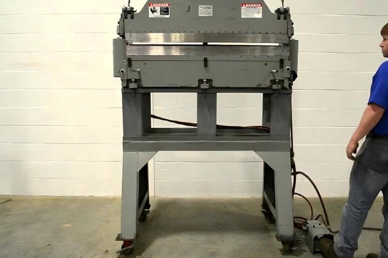
A common mistake is running a pneumatic press brake at its maximum capacity for extended periods. Unlike hydraulics with relief valves, pushing a toggle-linked pneumatic machine to the limit strains pivot pins and the frame. Another error is neglecting the air preparation unit (FRL – Filter, Regulator, Lubricator). Moisture in the lines causes corrosion and slow valve response, resulting in inconsistent bends. Operators also often ignore “dwell time.” Because air is compressible, the ram may need a brief pause at the stroke bottom to allow the material to fully form, especially for high-springback metals. Skipping this step can cause angle variations across a batch and reduce production consistency.
Industry Applications for Pneumatic Press Brakes
Pneumatic press brakes excel in industries where small, precision parts are the norm. In the electronics industry, they are used to bend aluminum chassis and shielding components with high repeatability. The HVAC sector utilizes them for ducting connectors and mounting brackets where the speed of the bend is more important than raw force. Medical device manufacturers favor them for their cleanliness, as the absence of hydraulic oil eliminates the risk of contamination in sensitive environments. Additionally, the appliance industry uses pneumatic machines for high-volume production of internal brackets and panels. In these settings, the machines are often integrated into automated cells where a robot loads and unloads parts at a pace that a hydraulic brake simply could not match.
Conclusion
Pneumatic press brakes offer an efficient solution for light-gauge sheet metal fabrication. Using compressed air, they provide a cost-effective alternative for bends within the 1–30-ton range. While they cannot match the raw force of hydraulic systems or the precision of high-end electric servos, their low maintenance, fast cycle times, and clean operation make them ideal for targeted manufacturing tasks. When choosing a machine, engineers should carefully evaluate tonnage needs and air quality to ensure reliable performance. In suitable applications, a pneumatic press brake is more than a secondary option—it becomes a strategic asset, improving efficiency, reducing downtime, and boosting overall shop floor productivity.
FAQ
What is the maximum thickness a pneumatic press brake can handle?
Typically, pneumatic press brakes are designed for light-gauge materials, usually up to 2mm (14 gauge) mild steel, depending on the bend length and die opening used.
Do pneumatic press brakes require a specialized air compressor?
They do not require a specialized compressor, but they do require a consistent supply of clean, dry air at a specific CFM (cubic feet per minute) rating and usually 6-8 bar of pressure to ensure consistent performance.
How does the accuracy of a pneumatic press brake compare to a hydraulic one?
For light-gauge materials, pneumatic brakes are highly accurate and repeatable. However, because air is compressible, they rely heavily on mechanical stops or precision toggle linkages to achieve the same level of depth control as hydraulic systems.
Are pneumatic press brakes safer than hydraulic ones?
Safety depends on the guarding system (like light curtains), but pneumatic brakes move much faster than hydraulic ones, meaning the reaction time of safety devices must be even quicker to prevent accidents.
Can I use standard press brake tooling on a pneumatic machine?
Yes, most modern pneumatic press brakes are designed to accept standard European or American style tooling, allowing for versatility across different machines in your shop.