Press Brake Tooling Guide: Punch and Die Selection for Different Bend Applications

Technical Overview of Press Brake Tooling
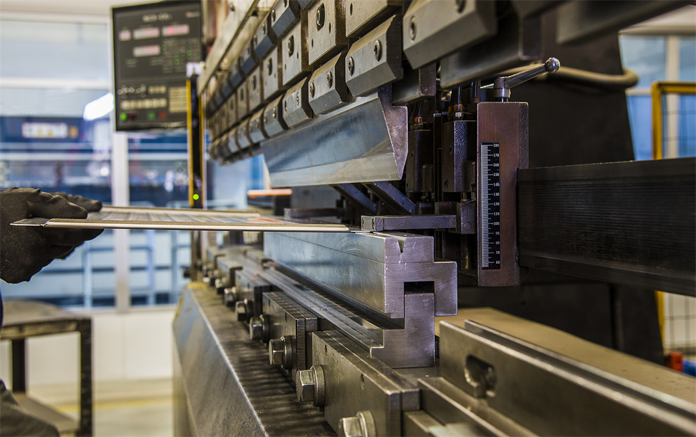
In the realm of modern metal fabrication, the efficiency and precision of a hydraulic press brake are not solely dependent on the machine’s CNC controller or hydraulic system. The interface between the machine and the workpiece—the tooling—plays a critical role in determining the final quality of the part. Press Brake Tooling: Punch Die Selection Different Bend Applications is a complex subject that requires a deep understanding of material science, geometry, and mechanical force. Tooling consists of two primary components: the upper tool (punch) and the lower tool (die). These components must be selected based on the material type, thickness, desired bend angle, and the specific geometry of the part being produced.
High-quality tooling is typically manufactured from high-carbon steel alloys, such as 42CrMo, which undergo induction hardening and precision grinding. This ensures that the tools can withstand the immense pressures required for air bending or bottoming without deforming. The hardening process usually achieves a Rockwell hardness (HRC) of 45 to 50, providing a balance between durability and toughness. When selecting tooling for HARSLE machines, operators must consider the compatibility of the tang (the part that fits into the ram) and the die rail, ensuring a secure and aligned fit for every operation.
The evolution of tooling has led to various standards, including European (Amada/Promecam), American, and New Standard (Wila/Trumpf) styles. Each style offers different clamping mechanisms and height profiles. Understanding these differences is the first step in optimizing your Press Brake Tooling: Punch Die Selection Different Bend Applications. For instance, European style tooling is widely favored for its versatility and ease of changeover, while New Standard tooling offers superior precision and automatic alignment features, making it ideal for high-end CNC operations.
Core Parameters of Punch and Die Selection
When diving into Press Brake Tooling: Punch Die Selection Different Bend Applications, several core parameters must be evaluated. The first is the punch tip radius. The radius of the punch determines the internal radius of the bend in bottoming and coining operations. In air bending, the internal radius is primarily a function of the die opening (V-opening), but the punch radius must still be smaller than the natural radius formed by the material to avoid ‘creasing’ or fracturing the metal. A general rule is that the punch radius should be close to, but not exceed, the material thickness for mild steel.
The second parameter is the punch angle. Punches are available in various angles, such as 90°, 88°, 60°, and 30°. The choice depends on the desired final angle and the amount of springback expected from the material. For example, an 88° punch is commonly used for 90° air bending in mild steel to compensate for the 2° of springback. For stainless steel, which has higher springback, a 30° or 45° acute punch might be necessary to achieve a 90° bend through over-bending.
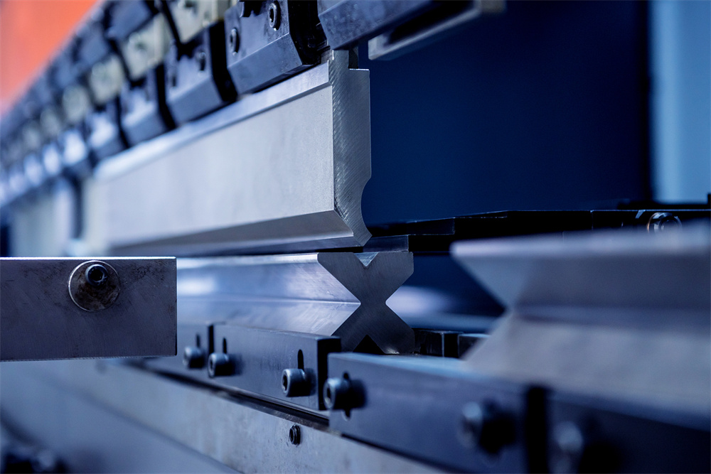
The third parameter is the die V-opening. The width of the V-opening affects the tonnage required to make the bend and the resulting internal radius. A wider V-opening reduces the required tonnage but increases the minimum flange length and the internal radius. Conversely, a narrow V-opening allows for smaller flanges but requires significantly more force, which can lead to tool wear or machine overload. Selecting the correct V-opening is the cornerstone of safe and accurate bending.
Finally, the punch shape or profile is essential for clearance. Standard straight punches are suitable for simple bends, but complex parts with return flanges require gooseneck punches. Gooseneck punches have a deep relief area that allows the previously bent flange to tuck inside the tool’s profile, preventing interference. Other shapes include sash punches for deep channels and acute punches for sharp angles and hemming operations.
Calculation Method for Tooling Selection
To master Press Brake Tooling: Punch Die Selection Different Bend Applications, one must be proficient in the mathematical formulas that govern the bending process. The most fundamental rule is the ‘8x Rule’ for V-opening selection. For materials up to 10mm thick, the ideal V-opening (V) is 8 times the material thickness (T). For materials thicker than 10mm, the V-opening is often increased to 10x or 12x the thickness to manage the extreme tonnage requirements.
The formula for calculating the required tonnage (P) per meter is: P = (650 x T² x L) / V, where T is the material thickness in mm, L is the length of the bend in meters, and V is the V-opening width in mm. This formula is for mild steel with a tensile strength of approximately 450 MPa. If you are bending stainless steel, you must multiply the result by a factor of 1.5 due to its higher tensile strength. Aluminum, being softer, requires a factor of approximately 0.5 to 0.8 depending on the alloy.
Another critical calculation is the minimum flange length (b). The minimum flange is the shortest distance from the edge of the sheet to the bend line that can be safely supported by the die. This is typically calculated as b = 0.7 x V. If the flange is shorter than this, the material will slip into the V-opening before the bend is completed, resulting in an inaccurate angle and potential damage to the workpiece. Understanding these calculations ensures that the Press Brake Tooling: Punch Die Selection Different Bend Applications is both safe and efficient.
Parameter Table for Standard Bending
The following table provides a quick reference for selecting the V-opening and estimating the required tonnage for mild steel (450 MPa) based on the 8x rule. This table is a vital tool for operators during the setup phase of Press Brake Tooling: Punch Die Selection Different Bend Applications.
| Material Thickness (mm) | Recommended V-Opening (mm) | Internal Radius (mm) | Min. Flange Length (mm) | Tonnage per Meter (T/m) |
|---|---|---|---|---|
| 1.0 | 8 | 1.3 | 5.6 | 8 |
| 1.5 | 12 | 2.0 | 8.4 | 12 |
| 2.0 | 16 | 2.6 | 11.2 | 16 |
| 3.0 | 24 | 4.0 | 16.8 | 24 |
| 4.0 | 32 | 5.3 | 22.4 | 32 |
| 6.0 | 48 | 8.0 | 33.6 | 48 |
| 8.0 | 64 | 10.6 | 44.8 | 64 |
| 10.0 | 80 | 13.3 | 56.0 | 80 |
Note: The internal radius in air bending is approximately 1/6th of the V-opening width (V/6). This is a critical estimation for designers when calculating bend deductions and flat patterns.
Common Engineering Mistakes in Tooling Selection
One of the most frequent mistakes in Press Brake Tooling: Punch Die Selection Different Bend Applications is overloading the tools. Every punch and die has a maximum tonnage limit per meter (T/m) engraved on its surface. Exceeding this limit can cause the tool to crack or explode, posing a significant safety risk. Operators often forget to adjust the tonnage calculation when switching from mild steel to stainless steel, leading to accidental tool damage.
Another common error is using a punch with a radius that is too small for the material. While it might seem intuitive to use a sharp punch for a sharp bend, a punch radius that is less than 63% of the material thickness can cause ‘sharp bending.’ This results in the punch digging into the material, creating a crease that weakens the bend and causes unpredictable springback. In high-stress applications, this crease can lead to structural failure of the part.
Ignoring the ‘interference zone’ is also a frequent issue. When bending complex shapes, the workpiece may collide with the punch or the ram during the second or third bend. This is why gooseneck punches are essential. Failing to simulate the bend sequence or check the tool clearance can result in ruined workpieces and wasted time. Modern CNC controllers on HARSLE machines offer 2D and 3D simulation to help avoid these collisions, but the operator must still select the correct tool profile initially.
Lastly, neglecting tool maintenance is a mistake that affects long-term accuracy. Dust, scale, and metal shavings can accumulate in the die or on the punch tip. If not cleaned, these particles can cause indentations on the workpiece or lead to uneven pressure distribution. Furthermore, using mismatched tool segments (mixing tools from different manufacturers or different wear levels) can cause variations in the bend angle across the length of the part.
Selection Checklist for Press Brake Tooling
To ensure the best results in Press Brake Tooling: Punch Die Selection Different Bend Applications, follow this comprehensive checklist before starting any job:
- Identify Material Properties: Determine the thickness, tensile strength, and springback characteristics of the metal.
- Determine the Bend Angle: Decide if you are air bending, bottoming, or coining. Air bending is most common for CNC machines.
- Select the V-Opening: Use the 8x rule (V = T x 8) as a starting point, adjusting for flange length requirements.
- Calculate Tonnage: Ensure the required tonnage does not exceed the machine’s capacity or the tool’s rated limit.
- Check Punch Radius: Ensure the punch tip radius is appropriate for the material thickness to avoid creasing.
- Verify Clearance: Use a gooseneck or sash punch if the part geometry suggests a risk of collision.
- Inspect Tool Condition: Check for chips, cracks, or wear on the working surfaces of the punch and die.
- Confirm Tool Alignment: Ensure the punch and die are perfectly centered to prevent ‘dog-leg’ bends or uneven angles.
- Lubrication: Apply appropriate bending lubricants if working with sensitive materials like polished stainless steel or aluminum to prevent galling.
Frequently Asked Questions (FAQ)
1. What is the difference between air bending and bottoming?
Air bending is a technique where the workpiece only touches the punch tip and the two edges of the die. The angle is determined by how deep the punch descends into the die. Bottoming involves pressing the material all the way to the bottom of the die, where the tool geometry dictates the final shape. Air bending is more versatile and requires less tonnage, while bottoming provides higher repeatability for specific angles.
2. How do I choose between a single V-die and a multi-V die?
Single V-dies are more precise and easier to align, making them ideal for high-precision CNC work. Multi-V dies (or 4-way dies) are cost-effective and space-saving for shops that handle a wide variety of material thicknesses but don’t require frequent tool changes. However, multi-V dies are heavier and more cumbersome to flip and align.
3. Why does my stainless steel bend differently than mild steel?
Stainless steel has a higher tensile strength and a higher coefficient of springback. This means it requires about 50% more pressure to bend and will ‘spring back’ more once the pressure is released. You must use a more acute punch angle and a larger V-opening to compensate for these factors.
4. Can I use a 90-degree punch for all bends?
No. While a 90-degree punch is standard, it cannot achieve angles sharper than 90 degrees. Furthermore, for air bending, you usually need an 88-degree or 85-degree punch to allow for springback. For acute bends (e.g., 30 or 45 degrees), you must use a specific acute punch and die set.
5. How often should I replace my press brake tooling?
Tooling life depends on the material being bent and the tonnage used. If you notice consistent inaccuracies in bend angles, visible wear on the punch tip, or ‘shouldering’ on the die, it is time to replace or regrind the tools. Precision-ground, hardened tools can last for years if properly maintained and not overloaded.
6. What is ‘Bend Deduction’ and how does tooling affect it?
Bend deduction is the amount of material you must subtract from the total length of your flanges to get the flat pattern length. It is directly influenced by the internal radius of the bend, which in turn is determined by the V-opening of the die. Changing your die selection will change your bend deduction, requiring a change in the flat part program.


