How Press Brake Backgauges Improve Bending Precision and Repeatability

Technical Overview of Press Brake Backgauges
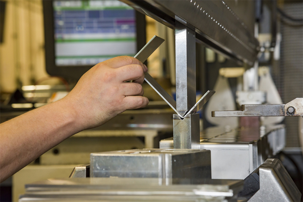
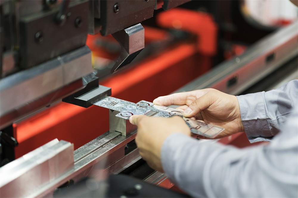
In the realm of modern metal fabrication, the press brake backgauge is often referred to as the ‘unsung hero’ of the workshop. While the hydraulic system and the tooling provide the force and the shape, the backgauge is responsible for the accuracy of the flange length and the consistency of the final product. A backgauge is a motorized or manual positioning system located at the rear of the press brake. Its primary function is to provide a physical stop for the workpiece, ensuring that the metal sheet is positioned correctly relative to the center of the die before the ram descends.
The evolution of backgauge technology has been a cornerstone in the transition from traditional manual fabrication to high-speed CNC (Computer Numerical Control) production. Early backgauges were simple mechanical stops that required manual adjustment for every different bend. Today, HARSLE and other leading manufacturers utilize multi-axis CNC backgauges driven by high-precision servo motors, ball screws, and linear guides. These systems can move into position in fractions of a second, allowing for complex, multi-bend sequences to be completed in a single handling of the part.
Precision in bending is defined by how closely the finished part matches the design specifications, while repeatability refers to the machine’s ability to produce the exact same result over hundreds or thousands of cycles. The backgauge directly influences both. By utilizing high-resolution encoders and rigid mechanical structures, modern backgauges eliminate the human error associated with manual measurement. This is particularly critical in industries like aerospace, medical device manufacturing, and electronics, where tolerances are measured in microns.
Furthermore, the complexity of a backgauge is often described by its ‘axes.’ A standard 2-axis backgauge typically controls the X-axis (depth) and the R-axis (height). However, more advanced systems can include Z1 and Z2 axes (lateral movement of the fingers) and even X-prime or Delta-X axes for tapered or asymmetrical bending. Each additional axis provides the operator with more flexibility, reducing setup times and increasing the overall throughput of the machine.
Core Parameters Influencing Bending Precision
To understand how press brake backgauges improve bending precision and repeatability, one must examine the core technical parameters that define their performance. The first and most critical parameter is Positioning Accuracy. This refers to the backgauge’s ability to reach a specific coordinate commanded by the CNC controller. High-end HARSLE machines often feature positioning accuracies within ±0.01mm to ±0.05mm. This level of precision is achieved through the use of precision-ground ball screws and high-torque servo motors that can overcome the friction and inertia of the gauge bar.
The second parameter is Repeatability. While accuracy tells you how close you are to the target, repeatability tells you how consistent you are at hitting that target repeatedly. In a production environment where a machine might perform 2,000 bends a day, even a tiny deviation can lead to significant scrap rates. Repeatability is maintained by the rigidity of the backgauge frame. If the frame flexes when the sheet metal is pushed against it, the bend will be inaccurate. Therefore, heavy-duty gauge bars and reinforced support structures are essential for maintaining repeatability under industrial loads.
Travel Speed is another vital parameter. While it doesn’t directly dictate the precision of the bend, it dictates the efficiency of the process. Modern CNC backgauges can move at speeds exceeding 300mm/s to 500mm/s. Fast travel speeds allow the backgauge to reposition itself while the operator is flipping or rotating the part, ensuring that the machine is always ready for the next stroke. This synchronization between the operator and the machine is what drives high-volume productivity.
Lastly, the Stroke Length of the various axes determines the maximum size of the part that can be bent. The X-axis stroke typically ranges from 500mm to 1000mm, while the R-axis (vertical) allows the fingers to move up and down to accommodate different die heights. Understanding these parameters is crucial for any fabricator looking to optimize their workflow and ensure that their equipment is capable of meeting the demands of modern engineering drawings.
Calculation Method for Backgauge Positioning
Calculating the correct backgauge position is a blend of geometry and material science. The CNC controller performs these calculations automatically, but understanding the underlying logic is essential for troubleshooting and advanced programming. The primary goal is to determine the distance from the center of the V-die to the backgauge finger. This distance is known as the ‘gauge dimension.’
The basic formula for a 90-degree bend is:
Gauge Position (X) = Desired Flange Length – (Material Thickness + Bend Deduction / 2)
However, this is a simplification. In reality, the calculation must account for several variables:
- Bend Deduction (BD): This is the amount of material that is ‘lost’ or ‘stretched’ during the bending process. It depends on the material type, the internal radius of the bend, and the width of the V-die.
- Material Thickness (T): Variations in material thickness (even within the same batch) can affect the gauge position. Advanced CNC systems use thickness sensors to adjust the backgauge in real-time.
- Die Height and Width: The R-axis must be calculated so that the backgauge fingers sit slightly above the top surface of the die, allowing the sheet to rest flat against the finger face without interference.
For complex parts with multiple bends, the controller must also calculate ‘clearance.’ If a previous bend is facing downward, the backgauge must move to a position that avoids colliding with the existing flange while still providing a stable stop for the current bend. This is where 3D simulation software becomes invaluable, as it allows the operator to visualize the backgauge movement and the part orientation before the first piece of metal is even loaded into the machine.
Backgauge Configuration Parameter Table
The following table compares common backgauge configurations found in HARSLE press brakes, highlighting how each configuration impacts precision and application range.
| Configuration | Axes Included | Primary Benefit | Typical Application | Precision Level |
|---|---|---|---|---|
| 2-Axis (Standard) | X, R | Cost-effective, handles 80% of standard bends. | Simple brackets, boxes, and panels. | High (±0.05mm) |
| 4-Axis (Advanced) | X, R, Z1, Z2 | Automatic lateral adjustment for different part widths. | Multi-stage bending, complex geometries. | Very High (±0.02mm) |
| 5-Axis (Specialized) | X, R, Z1, Z2, X-prime | Allows for tapered or conical bending. | Tapered poles, custom architectural metal. | Ultra High (±0.01mm) |
| 6-Axis (Premium) | X1, X2, R1, R2, Z1, Z2 | Independent movement for each finger; maximum flexibility. | High-precision aerospace and medical parts. | Ultra High (±0.01mm) |
Common Engineering Mistakes in Backgauge Operation
Even with the most advanced HARSLE CNC backgauge, errors can occur if the system is not managed correctly. One of the most common mistakes is neglecting calibration. Over time, mechanical vibrations and thermal expansion can cause the backgauge to drift from its zero point. If the operator does not perform a daily or weekly calibration check, the precision of the bends will slowly degrade, leading to parts that are out of tolerance.
Another frequent error is improper finger selection or maintenance. Backgauge fingers come in various shapes and sizes. Using a finger that is too narrow for a heavy plate can cause the plate to slip or the finger to deflect. Conversely, using a worn-out finger with a rounded edge will result in inconsistent flange lengths because the contact point with the metal sheet is no longer sharp and defined. Operators should regularly inspect the contact faces of the fingers for wear and tear.
Ignoring thermal expansion is a subtle but significant mistake in high-precision environments. As the machine runs, the hydraulic oil and the mechanical components heat up. This heat can cause the backgauge bar to expand slightly. In a 3-meter long machine, a small temperature change can result in a 0.1mm shift in position. High-end shops often operate in climate-controlled environments or use CNC controllers that have thermal compensation algorithms built into the software.
Finally, incorrect material handling can negate the precision of the backgauge. If the operator does not push the sheet firmly and squarely against the fingers, the bend will be crooked. This is why many modern systems include ‘sheet followers’ or ‘active sensors’ that detect when the sheet is properly seated against the backgauge before allowing the ram to move. Training operators on the importance of consistent material positioning is just as important as the technology itself.
Selection Checklist for Press Brake Backgauges
When investing in a new press brake or upgrading an existing system, choosing the right backgauge is critical for long-term ROI. Use this checklist to ensure you select a system that maximizes precision and repeatability:
- Assess Your Part Complexity: Do you mostly bend simple 90-degree flanges, or do you handle complex parts with varying widths and angles? If the latter, a 4-axis or 6-axis system is essential.
- Verify Positioning Accuracy and Repeatability: Ask for the manufacturer’s certified specs. For high-precision work, look for repeatability within ±0.02mm.
- Check the Drive System: Ensure the backgauge uses high-quality ball screws and linear guides rather than cheaper lead screws. Servo motors should be from reputable brands like Panasonic or Yaskawa.
- Evaluate the CNC Controller: Is the software intuitive? Does it support 3D visualization and automatic backgauge calculation? A powerful controller reduces setup time and prevents programming errors.
- Consider the Load Capacity: If you are bending heavy plates, the backgauge must be rugged enough to withstand the impact of the plate being pushed against it without losing calibration.
- Maintenance Accessibility: Is the backgauge easy to clean and lubricate? Systems with automatic lubrication or protected guide rails tend to last longer in dusty workshop environments.
- Safety Features: Does the backgauge have collision protection? The CNC should be able to detect if a finger is in the path of the tool to prevent expensive damage.
Frequently Asked Questions (FAQ)
1. How often should I calibrate my press brake backgauge?
For standard production, a weekly calibration check is recommended. However, for high-precision jobs or if the machine is running multiple shifts, a daily check at the start of the first shift is best practice. Most HARSLE CNC controllers have a built-in calibration routine that takes only a few minutes.
2. Can I upgrade a 2-axis backgauge to a 4-axis system later?
While some modular systems allow for upgrades, it is often technically difficult and expensive to add axes later because it requires new wiring, servo drives, and potentially a new CNC controller. It is almost always more cost-effective to purchase the required number of axes at the time of the initial machine purchase.
3. What is the difference between an X-axis and an R-axis?
The X-axis controls the depth of the backgauge (how far it moves toward or away from the operator), which determines the flange length. The R-axis controls the vertical height of the backgauge fingers, allowing them to move up or down to accommodate different die heights or to clear flanges that have already been bent.
4. Why are my flange lengths inconsistent even though the backgauge is moving correctly?
Inconsistency is often caused by material variations (thickness or hardness) or by the operator not holding the sheet flat against the die. It can also be caused by worn-out backgauge fingers or a loose connection in the ball screw assembly. Check for mechanical play in the gauge bar.
5. How does a backgauge help with ‘stage bending’?
Stage bending involves setting up multiple sets of tools along the length of the press brake to perform different bends in sequence. A multi-axis backgauge (specifically Z1 and Z2 axes) can automatically move the fingers to the correct lateral position for each tool set, allowing the operator to move the part from one station to the next without stopping to recalibrate.
6. Does the backgauge affect the bend angle?
Directly, no. The bend angle is determined by the depth of the ram (Y-axis). However, if the backgauge is not level or if the fingers are at different heights, the sheet may sit at an angle in the die, which can cause a ‘twist’ in the bend or an uneven angle across the length of the part.


