How to Identify and Resolve Material Feeding Problems in a Punching Machine


Introduction to Material Feeding in Punching Machines
In the world of high-speed metal fabrication, the efficiency of a punching machine is only as good as its material feeding system. Whether you are operating a mechanical power press or a sophisticated CNC turret punching machine, the ability to move material accurately and consistently into the die area is critical. When feeding issues arise, they don’t just slow down production; they lead to wasted material, damaged tooling, and potential safety hazards. To identify and resolve material feeding problems in a punching machine, one must understand the intricate balance between mechanical force, electronic control, and material properties.
HARSLE has long been at the forefront of developing robust punching solutions that minimize downtime. However, even the best machinery requires a keen eye for troubleshooting. Material feeding problems often manifest as subtle inaccuracies before escalating into catastrophic failures. This guide is designed to help operators and maintenance technicians diagnose the root causes of feeding inconsistencies and implement permanent solutions to maintain peak operational performance.
The feeding process involves several components working in perfect synchronization: the decoiler, the straightener, the feeder (NC or mechanical), and the punching unit itself. A failure in any of these stages can disrupt the entire workflow. By mastering the techniques to identify and resolve material feeding problems in a punching machine, you ensure that your fabrication shop remains competitive, cost-effective, and safe.
Key Considerations for Material Feeding Accuracy
Before diving into specific troubleshooting steps, it is essential to consider the variables that influence feeding accuracy. The first consideration is the material type and its physical condition. Different metals—such as aluminum, stainless steel, and galvanized steel—have varying coefficients of friction and surface finishes. For instance, oily or highly polished surfaces can cause slippage in roller-based feeders, while rough or scaled surfaces can cause excessive wear on the feeding components.
Another critical factor is the material’s thickness and width. Thin materials are prone to buckling if the feeding speed is too high or if the distance between the feeder and the die is unsupported. Conversely, heavy-gauge materials require significant torque from the feeder motor to overcome inertia and friction. Understanding the limitations of your specific feeder model in relation to the material specifications is the first step in preventing problems before they start.
Environmental factors also play a role. In many industrial settings, temperature fluctuations can affect the viscosity of lubricants used on the material or within the machine’s mechanical parts. Dust and metal shavings can accumulate on the rollers or sensors, leading to false readings or physical obstructions. A clean and controlled environment is often the unsung hero of consistent material feeding.
Finally, the synchronization between the press stroke and the feeder movement is paramount. In a mechanical setup, this is often controlled by a cam or a linkage system. In modern CNC systems, it is managed by high-speed encoders and PLC logic. If the timing is off by even a fraction of a second, the material may still be moving when the punch makes contact, leading to elongated holes, broken punches, or severe machine vibration.
Technical Details: Identifying the Root Causes
1. Recognizing Slippage and Grip Issues
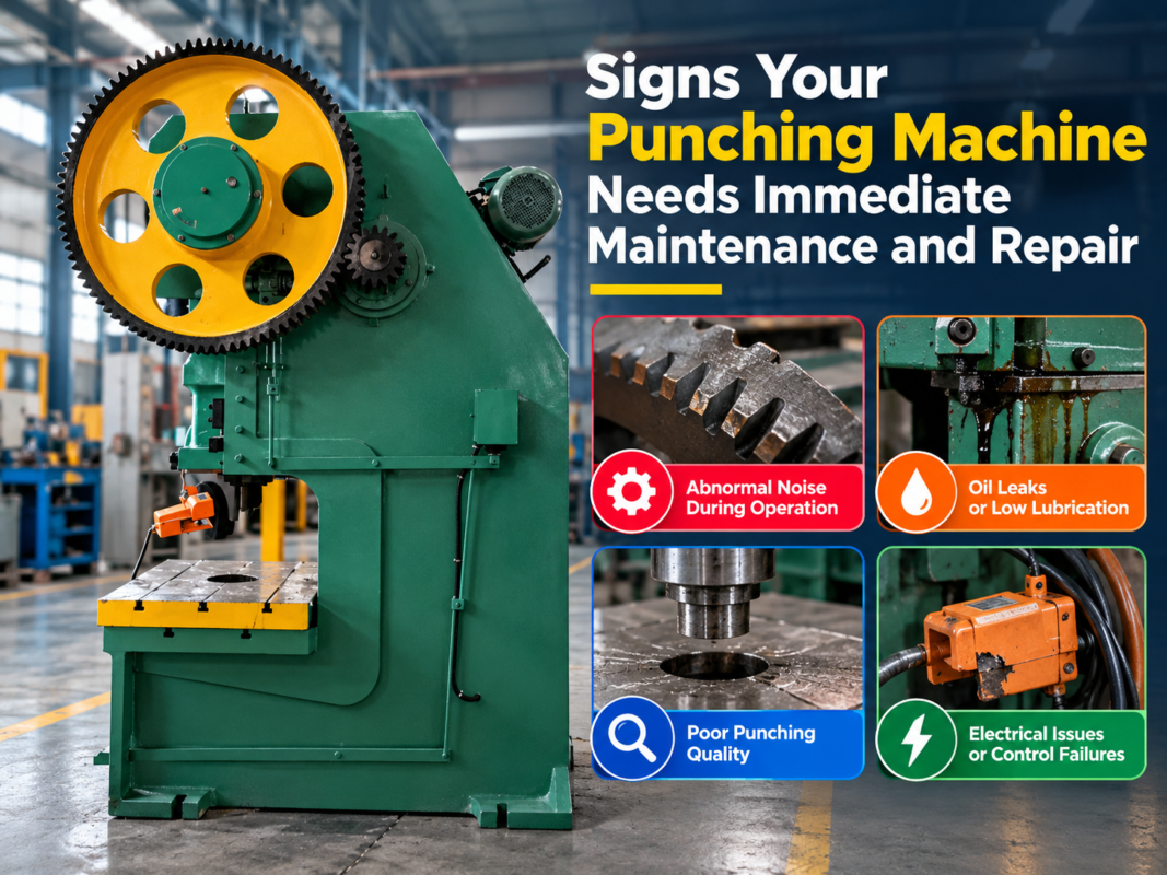
Slippage is perhaps the most common feeding problem. It occurs when the feeder rollers rotate, but the material does not move the corresponding distance. You can identify this by measuring the actual length of the fed material against the programmed value. If the holes are consistently “short,” slippage is likely the culprit. Look for “burn marks” or shiny spots on the material surface, which indicate that the rollers have been spinning against a stationary sheet.
To resolve this, check the roller pressure. Most NC feeders allow for pneumatic or spring-loaded pressure adjustments. If the pressure is too low, the rollers won’t grip; if it’s too high, you risk deforming the material or damaging the roller bearings. Additionally, inspect the rollers for wear. Over time, the knurled or polyurethane surface of the rollers can smooth out, losing the necessary friction to move the material effectively.
2. Diagnosing Misalignment and “Walking”
Misalignment, often called “walking,” happens when the material drifts to one side as it passes through the feeder. This results in parts that are out of square or holes that are not centered on the strip. To identify this, check the guide rails. If the material is pressing hard against one side of the guide, the feeder is likely not aligned perfectly with the center line of the die.
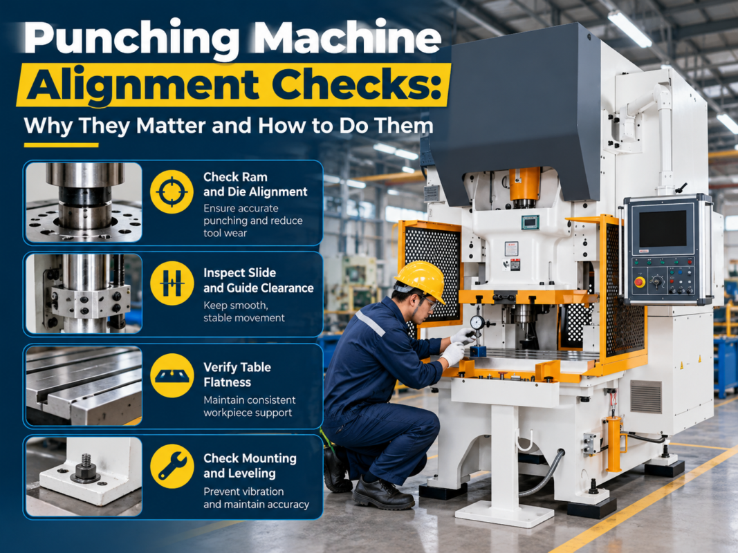
Resolution involves a two-step process. First, ensure the feeder itself is physically squared to the punching machine. Use precision levels and squares to verify the geometry. Second, check the material guides. They should be tight enough to prevent lateral movement but loose enough to allow the material to slide freely without binding. If the material is coiled, ensure the decoiler is also aligned with the feeder to prevent “camber” issues from the start.
3. Detecting Timing and Synchronization Errors
Timing errors are often the hardest to identify because they happen in milliseconds. If you notice that the material is buckling between the feeder and the die, or if the pilot pins in the die are breaking frequently, the feeder is likely out of sync with the press. In an NC system, this could be due to a faulty encoder signal or incorrect parameters in the control unit.
To resolve timing issues, review the “feed angle” settings in your machine’s controller. The feed must be completed while the punch is in the upper portion of its stroke. If the feed starts too early or ends too late, the material will be trapped by the stripper plate or the punch itself. Testing at a lower SPM (strokes per minute) can help you visually confirm when the material starts and stops moving in relation to the ram position.
Technical Details: Resolving Material-Specific Challenges
Handling Thin and Flexible Materials
Thin materials (under 0.5mm) present a unique challenge: buckling. Because they lack structural rigidity, any resistance in the die or a slight over-feed can cause the material to fold like an accordion. To resolve this, many HARSLE machines utilize a “bridge” or a support plate between the feeder and the tool. This keeps the material flat and constrained. Additionally, reducing the acceleration and deceleration ramps in the servo controller can prevent the sudden jerks that lead to buckling.
Managing Heavy-Gauge and High-Strength Steels
When working with thick or high-tensile materials, the primary issue is inertia. The feeder must work much harder to start and stop the heavy mass of the material. This can lead to motor overheating or “overshooting” the target position. To resolve this, ensure that your feeder is equipped with a robust braking system and a high-torque servo motor. It may also be necessary to use a loop control system with a decoiler to ensure there is always a slack “loop” of material, reducing the weight the feeder has to pull directly.
Selection Advice: Choosing the Right Feeder for Your Machine
When looking to identify and resolve material feeding problems in a punching machine, sometimes the resolution is realizing that the current feeder is not suited for the job. When selecting a new system or upgrading an existing HARSLE machine, consider the following:
- NC Servo Feeders vs. Mechanical Feeders: NC feeders offer much higher flexibility, allowing you to change feed lengths via a touch screen. They are ideal for shops that run multiple different parts. Mechanical feeders are excellent for dedicated, high-speed long runs but are harder to adjust.
- Roller Material: Choose hardened steel rollers for heavy-duty applications and polyurethane-coated rollers for sensitive materials like pre-painted or polished aluminum to prevent surface scratching.
- Pilot Release Function: Ensure the feeder has a high-speed pilot release. This allows the material to be “released” momentarily so the die’s pilot pins can perfectly center the material before the punch hits. This is crucial for progressive die work.
- Integration Capabilities: The feeder should communicate seamlessly with the punching machine’s emergency stop and stroke-control circuits.
Investing in a high-quality feeder from a reputable manufacturer like HARSLE ensures that you have the technical support and spare parts availability necessary to keep your production line moving. A well-matched feeder reduces the frequency of the very problems we’ve discussed, leading to a much higher Return on Investment (ROI).
Maintenance Checklist for Feeding Systems
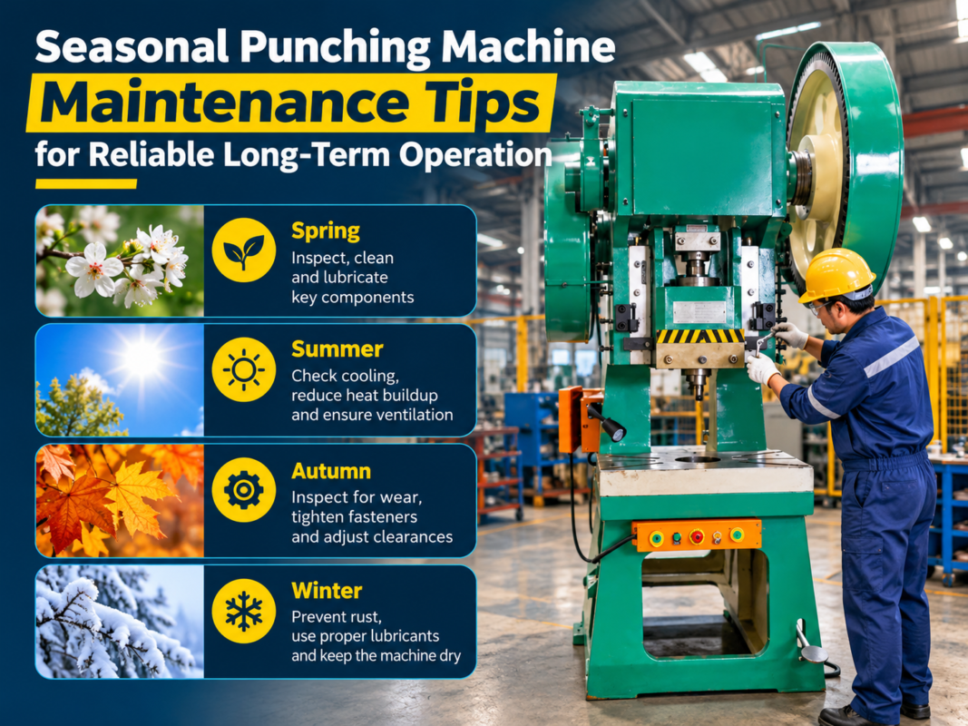
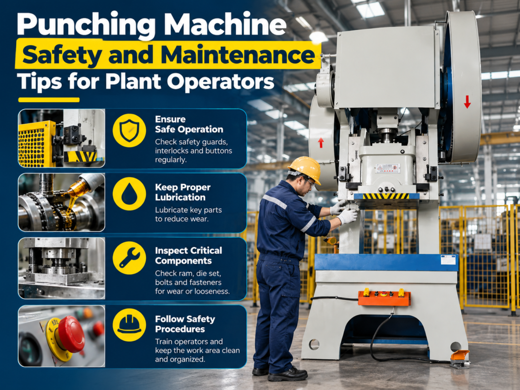
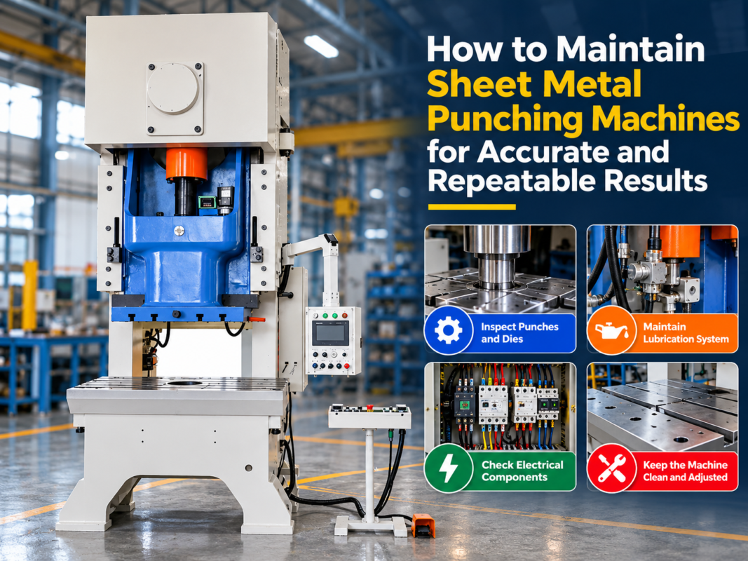
Preventative maintenance is the best way to avoid having to identify and resolve material feeding problems in a punching machine during a critical production run. Follow this checklist to keep your system in top shape:
| Component | Action Required | Frequency |
|---|---|---|
| Feed Rollers | Clean with solvent to remove oil and debris; check for wear. | Daily |
| Pneumatic Lines | Check for leaks and ensure consistent air pressure. | Weekly |
| Drive Belts/Gears | Inspect for tension and signs of fraying or cracking. | Monthly |
| Servo Motor/Encoder | Check cable connections and clear any dust from cooling fans. | Quarterly |
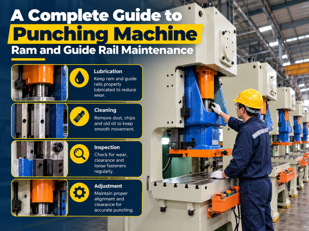
| Lubrication Points | Apply grease to bearings and sliding guides as per manual. | Monthly |
Frequently Asked Questions (FAQ)
Why is my punching machine feeding inconsistent lengths?
Inconsistent lengths are usually caused by material slippage, fluctuating air pressure in the feeder’s gripping mechanism, or an encoder that is slipping on the motor shaft. Check the roller tension and ensure the material is clean and free of excessive oil.
How do I stop the material from wrinkling during the feed?
Wrinkling or buckling usually happens with thin materials. You can resolve this by installing a material support bridge between the feeder and the die, or by slowing down the feeding acceleration speed in the CNC settings.
Can I use one feeder for all types of metal?
While many feeders are versatile, you may need to change the roller type or adjust the pressure settings when switching between very soft metals (like aluminum) and very hard metals (like stainless steel) to prevent marking or slippage.
What is the role of the pilot release in material feeding?
The pilot release momentarily opens the feeder rollers just before the punch hits. This allows the material to be moved slightly by the pilot pins in the die, ensuring perfect alignment that the feeder alone might not achieve.
How often should I calibrate my NC feeder?
Calibration should be checked whenever you change material thickness or if you notice a trend in dimensional inaccuracies. A quick check once a week is a good practice for high-precision shops.
Conclusion
The ability to identify and resolve material feeding problems in a punching machine is a vital skill for any modern fabricator. By understanding the mechanical and electronic nuances of your feeding system, you can transform a frustrating production bottleneck into a streamlined, high-efficiency process. Remember that most feeding issues stem from simple causes: improper tension, misalignment, or lack of maintenance. By following the technical advice and maintenance protocols outlined in this guide, you can maximize the lifespan of your HARSLE equipment and ensure the highest quality for every part produced.
In the competitive landscape of metal fabrication, precision is everything. Don’t let a minor feeding glitch compromise your reputation or your bottom line. Stay proactive, keep your machinery clean, and always choose high-quality components designed for the rigors of industrial use. With the right approach, your punching machine will continue to be the reliable workhorse your business depends on.